User:Clh288~commonswiki/gallery
Jump to navigation
Jump to search
Sun Sep 23 17:46:40 EDT 2007
[edit]-
The drivers side of the engine compartment of a 4th gen maxima
Sun Sep 23 17:45:12 EDT 2007
[edit]-
A air filter being installed in a 4th gen maxima.
Sun Sep 23 17:37:58 EDT 2007
[edit]-
The airfelter conpairment on a 4th gen maxima.
-
The engine of a 4th generation Nessin Maxima
Sun Sep 23 15:46:57 EDT 2007
[edit]-
Picture of ECU cover on a 1995 nissan maxima. This apples to 4th generation maximas (95-99) This is the work of myself Clh288, I release this image in to the pubice domain.
-
Picture of ECU on a 1995 nissan maxima. This apples to 4th generation maximas (95-99). This is the work of myself Clh288, I release this image in to the pubice domain.
Sun Sep 23 15:40:53 EDT 2007
[edit]errors
[edit]- Image:Auto_repair_Maxima_4th_gen_ECU_#1.JPG UploadForbiddenException uploading a file with this name is forbidden
- Image:Auto_repair_Maxima_4th_gen_ECU_#2.JPG UploadForbiddenException uploading a file with this name is forbidden
-
Picture of ECU cover on a 1995 nissan maxima. This apples to 4th generation maximas (95-99) This is the work of myself Clh288, I release this image in to the pubice domain.
-
Picture of ECU on a 1995 nissan maxima. This apples to 4th generation maximas (95-99). This is the work of myself Clh288, I release this image in to the pubice domain.
Wed Aug 01 21:59:55 EDT 2007
[edit]errors
[edit]- Image:dionecassinibig.jpg UploadForbiddenException uploading a file with this name is forbidden
Wed Aug 01 21:57:09 EDT 2007
[edit]errors
[edit]- Image:dione3_cassini_big.jpg UploadForbiddenException uploading a file with this name is forbidden
Wed Aug 01 21:53:40 EDT 2007
[edit]errors
[edit]- Image:dione3_cassini_big.jpg UploadForbiddenException uploading a file with this name is forbidden
Fri Jul 06 23:49:37 EDT 2007
[edit]Mon Jun 18 21:21:26 EDT 2007
[edit]Fri Jun 15 10:31:46 EDT 2007
[edit]Sun Jun 10 16:58:04 EDT 2007
[edit]-
President Dwight D. Eisenhower meets with Harold Stasson, a special assistant who was largely responsible for drafting the "Open Skies" proposal, in the Oval Office on March 22, 1955.
-
The first test launch of the Vanguard launch vehicle for the U.S.-IGY Earth Satellites Program to place a satellite in Earth orbit to determine atmospheric density and conduct geodetic measurements. A malfunction in the first stage caused the vehicle to lose thrust after two seconds, and the vehicle was destroyed.
-
Icing research is under way during the 1940s at the Lewis Research Center in Cleveland, Ohio, one of the NACA's original facilities that became part of NASA.
-
This photo shows the original twelve-foot pressure wind tunnel at the Ames Research Center in Mountain View, California, shortly after its construction in 1946. Ames was another NACA facility that became part of NASA. (NASA photo 94-H-418)
-
The full-scale wind tunnel at the Langley Research Center in Hampton, Virginia. While Langley had a rich heritage in aeronautics work, engineers and scientists at Langley also became involved in space exploration with the birth of NASA. (NASA photo 90-H-190)
-
NASA Administrator T. Keith Glennan shows Associate Administrator Robert C. Seamans a model of the Mercury Redstone rocket on July 19, 1960.
-
President Lyndon B. Johnson addresses space workers at Cape Kennedy, Florida, on September 15, 1964. NASA Administrator James E. Webb is in the background. (NASA photo 64-H-2365)
-
The announcement of plans for the building and launching of th world's first artificial satellite on July 29, 1955. Presidential press secretary James Hagerty is shown with five scientists during the meeting at which the announcement of President Eisenhower's approval of the plan was made. Front, left to right: Dr. Alan T. Waterman, Hagerty, Dr. S. Douglas Cornell, and Dr. Alan Shapley. Standing, left to right: Dr. J. Wallace Joyce and Dr. Athelstan Spilhaus.
-
Sergei P. Korolev (1906–1966), Russian rocket and spacecraft pioneer.
-
The announcement by the Soviets of the intention to launch an Earth satellite during the IGY. This photo was taken at the Legation of the Soviet Union in Copenhagen, Denmark, during the 6th International Astronautical Congress, August 1955, shortly after the Americans announced their intentions to launch a satellite. Left to right: Mr. Vereschetin and Mr. Sannikov of Soviet State Security; Kyrill F. Ogorodikov, professor of astronomy, Leningrad University; and Leonid Ivanovich Sedov, specialist in mechanics, Soviet Academy of Sciences.
-
Before a national television audience, President Dwight D. Eisenhower displays a nose cone from a Jupiter-C missile on August 7, 1957.
-
The Sputnik I spacecraft.
-
An exploded view of the Sputnik I spacecraft.
-
Explorer I sits on the launch pad venting before launch, January 31, 1958. (NASA photo 97-H-482)
-
Dr. William H. Pickering, Dr. James A. Van Allen, and Dr. Wernher von Braun (left to right) hoist a model of Explorer I and the final stage after the successful launching on January 31, 1958. (NASA photo 78-H-136)
-
The cover of the S:NASA's Origins and the Dawn of the Space Age
-
Sig from the S:NASA's Origins and the Dawn of the Space Age
Tue Jun 05 21:46:03 EDT 2007
[edit]Tue Jun 05 21:41:05 EDT 2007
[edit]Tue Jun 05 21:25:41 EDT 2007
[edit]Tue Jun 05 21:21:39 EDT 2007
[edit]Tue Jun 05 21:20:04 EDT 2007
[edit]errors
[edit]- Image:-M.png UnexpectedAnswerException unexpected response data (SimpleAction) status HTTP/1.0 200 OK
Tue Jun 05 21:11:55 EDT 2007
[edit]errors
[edit]- Image:-M.png UnexpectedAnswerException unexpected response data (SimpleAction) status HTTP/1.0 200 OK
Mon Jun 04 23:16:07 EDT 2007
[edit]Mon Jun 04 22:59:30 EDT 2007
[edit]Mon Jun 04 22:21:23 EDT 2007
[edit]Mon Jun 04 21:49:43 EDT 2007
[edit]Mon Jun 04 21:26:43 EDT 2007
[edit]Mon Jun 04 14:15:51 EDT 2007
[edit]Mon Jun 04 13:47:40 EDT 2007
[edit]Sun Jun 03 23:11:10 EDT 2007
[edit]Sun Jun 03 21:23:26 EDT 2007
[edit]Sun Jun 03 20:00:31 EDT 2007
[edit]Sun Jun 03 19:10:05 EDT 2007
[edit]Sun Jun 03 16:22:43 EDT 2007
[edit]Sun Jun 03 15:09:30 EDT 2007
[edit]Sun Jun 03 14:40:04 EDT 2007
[edit]Sun Jun 03 14:35:58 EDT 2007
[edit]Sun Jun 03 14:28:41 EDT 2007
[edit]Thu May 31 12:45:15 EDT 2007
[edit]-
Figure 3-6. Cosmos 1686. Note the Merkur capsule (left), heavily modified to house scientific instruments.
-
Figure 3-7. Cosmos 1686 and Salyut 7.
-
Figure 3-8. Kvant module.
-
Figure 3-9. Kvant 2 module. Kvant 2 houses an EVA airlock (hatch visible at left).
-
Figure 3-10. Lyappa arm. Modules for Mir’s lateral ports first dock at the front longitudinal port. Each module carries a Lyappa arm (top), which attaches to a socket (bottom) on the outside of the Mir multiport node. The arm then pivots the module to the proper lateral berthing port.
-
Figure 3-11. Repositioning Kvant module using Lyappa arm.
-
Figure 3-12. Kristall module. Kristall joined Mir in 1990. It carries two APAS-89 docking units (left).
-
Figure 3-13. APAS-89 androgynous docking unit.
-
Figure 3-15. Polyus cutaway. Displays the FGB-based service/propulsion module. Note that, like other FGBbased vehicles, it launched aft end up. This places Polyus’ front end at the bottom. The streamlined projections on Polyus’ sides were dispensers for experimental tracking targets.
-
Figure 3-14. Kvant and FSM. The streamlined fairing covering the aft end of the FSM (right) pointed upwards at liftoff, and formed the nose of the launch stack.
-
Figure 3-16. Polyus satellite on Energia launch vehicle.
Thu May 31 12:05:12 EDT 2007
[edit]-
This false-color mosaic of the central region of the Coma cluster combines infrared and visible-light images to reveal thousands of faint objects (green). Follow-up observations showed that many of these objects, which appear here as faint green smudges, are dwarf galaxies belonging to the cluster. Two large elliptical galaxies, NGC 4889 and NGC 4874, dominate the cluster's center. The mosaic combines visible-light data from the Sloan Digital Sky Survey (color coded blue) with long- and short-wavelength infrared views (red and green, respectively) from NASA's Spitzer Space Telescope.
Wed May 30 22:30:58 EDT 2007
[edit]-
Figure 3-5. Cutaway of TKS vehicle. Details are conjectural. The broad black line outlines the vehicle’s pressurized compartments. A tunnel (stippled) connects the FGB and Merkur capsule.
Wed May 30 21:57:24 EDT 2007
[edit]Tue May 29 22:44:40 EDT 2007
[edit]-
The sharpest image ever taken of the large "grand design" spiral galaxy M81 is being released today at the American Astronomical Society Meeting in Honolulu, Hawaii. This beautiful galaxy is tilted at an oblique angle on to our line of sight, giving a "birds-eye view" of the spiral structure. The galaxy is similar to our Milky Way, but our favorable view provides a better picture of the typical architecture of spiral galaxies. Though the galaxy is 11.6 million light-years away, NASA Hubble Space Telescope's view is so sharp that it can resolve individual stars, along with open star clusters, globular star clusters, and even glowing regions of fluorescent gas. The spiral arms, which wind all the way down into the nucleus, are made up of young, bluish, hot stars formed in the past few million years. They also host a population of stars formed in an episode of star formation that started about 600 million years ago. The greenish regions are dense areas of bright star formation. The ultraviolet light from hot young stars are fluorescing the surrounding clouds of hydrogen gas. A number of sinuous dust lanes also wind all the way into the nucleus of M81. The galaxy's central bulge contains much older, redder stars. It is significantly larger than the Milky Way's bulge. A black hole of 70 million solar masses resides at the center of M81. The black hole is about 15 times the mass of the Milky Way's black hole. Previous Hubble research shows that the size of the central black hole in a galaxy is proportional to the mass of a galaxy's bulge. M81 may be undergoing a surge of star formation along the spiral arms due to a close encounter it may have had with its nearby spiral galaxy NGC 3077 and a nearby starburst galaxy (M82) about 300 million years ago. Astronomers plan to use the Hubble image to study the star formation history of the galaxy and how this history relates to the neutron stars and black holes seen in X-ray observations of M81 with NASA's Chandra X-ray Observatory. M81 is one of the brightest galaxies that can be seen from the Earth. It is high in the northern sky in the circumpolar constellation Ursa Major, the Great Bear. At an apparent magnitude of 6.8 it is just at the limit of naked-eye visibility. The galaxy's angular size is about the same as that of the Full Moon. The Hubble data was taken with the Advanced Camera for Surveys in 2004 through 2006. This color composite was assembled from images taken in blue, visible, and infrared light.
Tue May 29 21:17:48 EDT 2007
[edit]-
Figure 3-2. FGB. This is a simplified aft view of the propulsion/cargo module used in the TKS vehicles and as the basis for subsequent space station modules and tugs. Aft (left) details are conjectural. Solar arrays are omitted for clarity.
-
Figure 3-3. TKS. The FGB and Merkur vehicles were joined together aft end to aft end to form a TKS; thus, this is a front view of the conical Merkur capsule (left), and an aft view of the FGB (right).
-
Figure 3-4. Merkur capsule.
Tue May 29 12:46:06 EDT 2007
[edit]Tue May 29 12:05:21 EDT 2007
[edit]Tue May 29 01:24:19 EDT 2007
[edit]Mon May 28 22:00:46 EDT 2007
[edit]Mon May 28 19:41:31 EDT 2007
[edit]Mon May 28 19:21:45 EDT 2007
[edit]Mon May 28 18:15:29 EDT 2007
[edit]Sun May 27 20:33:47 EDT 2007
[edit]-
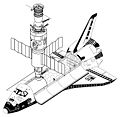
Figure 4-4. Space Shuttle Orbiter and Soyuz-TM (drawn to scale). Current spacecraft used by humans to travel in space.
Sun May 27 19:53:49 EDT 2007
[edit]-
Figure 4-3. Apollo CSM (top) and L2 (drawn to scale). Command ships for the Moon voyage.
Sun May 27 19:44:01 EDT 2007
[edit]-
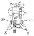
Figure 4-2. L3 (left) and Apollo LM (drawn to scale). Manned Moon landers.
Sun May 27 19:34:57 EDT 2007
[edit]-
Figure 4-1. Saturn V (left) and N-1 (drawn to scale). Manned Moon rockets.
Sun May 27 14:40:29 EDT 2007
[edit]-
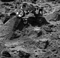
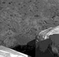
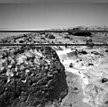
The "Mini Matterhorn" is a 3/4 meter rock immediately east-southeast of the Mars Pathfinder lander. This image, along with PIA00817 and PIA00818, shows how super resolution techniques can be applied to nearfield targets to help to address questions about the texture of the rocks at the landing site and what it might tell us about their modes of origin. This image shows a "raw", standard-resolution color frame of the rock. PIA00818 and PIA00819 were produced by combining the "Super pan" frames from the IMP camera. The composite color frame consists of 7 frames from the right eye, taken with different color filters that were enlarged by 500% and then co-added using Adobe Photoshop to produce, in effect, a super-resolution panchromatic frame that is sharper than an individual frame would be. Mars Pathfinder is the second in NASA's Discovery program of low-cost spacecraft with highly focused science goals. The Jet Propulsion Laboratory, Pasadena, CA, developed and manages the Mars Pathfinder mission for NASA's Office of Space Science, Washington, D.C. JPL is a division of the California Institute of Technology (Caltech).
-
The "Mini Matterhorn" is a 3/4 meter rock immediately east-southeast of the Mars Pathfinder lander. This image, along with PIA00816 and PIA00818, shows how super resolution techniques can be applied to nearfield targets to help to address questions about the texture of the rocks at the landing site and what it might tell us about their modes of origin. PIA00816 shows a "raw", standard-resolution color frame of the rock. This image and PIA00818 were produced by combining the "Super pan" frames from the IMP camera. The composite color frame consists of 7 frames from the right eye, taken with different color filters that were enlarged by 500% and then co-added using Adobe Photoshop to produce, in effect, a super-resolution panchromatic frame that is sharper than an individual frame would be. This panchromatic frame was then colorized with the red, green, and blue filtered images from the same sequence. The color balance was adjusted to approximate the true color of Mars. Mars Pathfinder is the second in NASA's Discovery program of low-cost spacecraft with highly focused science goals. The Jet Propulsion Laboratory, Pasadena, CA, developed and manages the Mars Pathfinder mission for NASA's Office of Space Science, Washington, D.C. JPL is a division of the California Institute of Technology (Caltech).
-
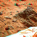
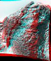
The "Mini Matterhorn" is a 3/4 meter rock immediately east-southeast of the Mars Pathfinder lander. This image, along with PIA00816 and PIA00817 shows how super resolution techniques can be applied to nearfield targets to help to address questions about the texture of the rocks at the landing site and what it might tell us about their modes of origin. PIA00816 shows a "raw", standard-resolution color frame of the rock. This image and PIA00817 were produced by combining the "Super pan" frames from the IMP camera. The composite color frame consists of 7 frames from the right eye, taken with different color filters that were enlarged by 500% and then co-added using Adobe Photoshop to produce, in effect, a super-resolution panchromatic frame that is sharper than an individual frame would be. The anaglyph view of Mini Matterhorn was produced by combining the left and right eye frames by assigning the left eye view to the red color plane and the right eye view to the green and blue color planes (cyan), to produce a stereo anaglyph mosaic. This mosaic can be viewed in 3-D on your computer monitor or in color print form by wearing red-blue 3-D glasses. Mars Pathfinder is the second in NASA's Discovery program of low-cost spacecraft with highly focused science goals. The Jet Propulsion Laboratory, Pasadena, CA, developed and manages the Mars Pathfinder mission for NASA's Office of Space Science, Washington, D.C. JPL is a division of the California Institute of Technology (Caltech).
-
Barnacle Bill is a small rock immediately west-northwest of the Mars Pathfinder lander and was the first rock visited by the Sojourner Rover's alpha proton X-ray spectrometer (APXS) instrument. This image and PIA00820 show super resolution techniques applied to the first APXS target rock, which was never imaged with the rover's forward cameras. Super resolution was applied to help to address questions about the texture of this rock and what it might tell us about its mode of origin. These views of Barnacle Bill were produced by combining the "Insurance Pan" frames taken while the IMP camera was still in its stowed position on sol2. The composite color frame consists of 5 frames from the right eye, taken with different color filters that were enlarged by 500% and then co-added using Adobe Photoshop to produce, in effect, a super-resolution panchromatic frame that is sharper than an individual frame would be. The anaglyph view of Barnacle Bill was produced by combining the left (single red-filtered image) with the right eye frames by assigning the left eye view to the red color plane and the right eye view to the green and blue color planes (cyan), to produce a stereo anaglyph mosaic. This mosaic can be viewed in 3-D on your computer monitor or in color print form by wearing red-blue 3-D glasses. Mars Pathfinder is the second in NASA's Discovery program of low-cost spacecraft with highly focused science goals. The Jet Propulsion Laboratory, Pasadena, CA, developed and manages the Mars Pathfinder mission for NASA's Office of Space Science, Washington, D.C. JPL is a division of the California Institute of Technology (Caltech).
-
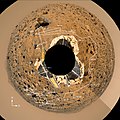
This image is one frame of an animation that was created by using two mosaics: a color image of the Gallery Pan and an image which indicates the distance to the nearest object at each pixel location, referred to as a range image. The range data set is treated as a displacement map with respect to a sphere's surface, and the color image mosaic is draped onto the inside of the sphere. The position of the camera is fixed at the sphere's center, while its viewing direction is in this case looking at the south pole of the sphere. The mosaics were projected onto a continuous cylindrical/perspective coordinate system spanning 360 degrees of azimuth. The distortion visible near the edges of this image is due to the large field of view, as well as the limitation introduced by using cylindrically-projected images on the sphere - the effects of which are less apparent when smaller fields of view are used. The image has been rotated so that the main points of interest, which are the "Rock Garden," the rover Sojourner and the rock "Yogi," are easily seen arching across the upper hemisphere. In fixed Mars Surface coordinates, the top of the image looks out towards a point a few degrees north of West. Color has been enhanced to improve contrast in features, and is derived from IMP spectral filters 5, 9 and 0. Mars Pathfinder is the second in NASA's Discovery program of low-cost spacecraft with highly focused science goals. The Jet Propulsion Laboratory, Pasadena, CA, developed and manages the Mars Pathfinder mission for NASA's Office of Space Science, Washington, D.C. JPL is a division of the California Institute of Technology (Caltech).
-
Each of these panoramic views is a controlled mosaic of approximately 300 IMP images covering 360 degrees of azimuth and elevations from approximately 4 degrees above the horizon to 45 degrees below it. Simultaneous adjustment of orientations of all images has been performed to minimize discontinuities between images. Mosaics have been highpass-filtered and contrast-enhanced to improve discrimination of details without distorting relative colors overall. TOP IMAGE: Enhanced true-color image created from the "Gallery Pan" sequence, acquired on sols 8-10 so that local solar time increases nearly continuously from about 10:00 at the right edge to about 12:00 at the left. Mosaics of images obtained by the right camera through 670 nm, 530 nm, and 440 nm filters were used as red, green and blue channels. Grid ticks indicate azimuth clockwise from north in 30 degree increments and elevation in 15 degree increments. BOTTOM IMAGE: Anaglyphic stereoimage created from the "monster pan" sequence, acquired in four sections between about 8:30 and 15:00 local solar time on sol 3. Mosaics of images obtained through the 670 nm filter (left camera) and 530 and 440 nm filters (right camera) were used where available. At the top and bottom, left- and right-camera 670 nm images were used. Part of the northern horizon was not imaged because of the tilt of the lander. This image may be viewed stereoscopically through glasses with a red filter for the left eye and a cyan filter for the right eye. NOTE: original caption as published in Science Magazine Mars Pathfinder is the second in NASA's Discovery program of low-cost spacecraft with highly focused science goals. The Jet Propulsion Laboratory, Pasadena, CA, developed and manages the Mars Pathfinder mission for NASA's Office of Space Science, Washington, D.C. JPL is a division of the California Institute of Technology (Caltech).
-
Planimetric (overhead view) map of the landing site, to a distance of 20 meters from the spacecraft. North is at the top in this and Plates 3-5. To produce this map, images were geometrically projected onto an assumed mean surface representing the ground. Features above the ground plane (primarily rocks) therefore appear displaced radially outward; the amount of distortion increases systematically with distance. The upper surfaces of the lander and rover also appear enlarged and displaced because of their height. Primary grid (white) is based on the Landing Site Cartographic (LSC) coordinate system, defined with X eastward, Y north, and Z up, and origin located at the mean ground surface immediately beneath the deployed position of the IMP camera gimbal center. Secondary ticks (cyan) are based on the Mars local level (LL) frame, which has X north, Y east, Z down, with origin in the center of the lander baseplate. Rover positions (including APXS measurements) are commonly reported in the LL frame. Yellow grid shows polar coordinates based on the LSC system. Cartographic image processing by U.S. Geological Survey. NOTE: original caption as published in Science Magazine Mars Pathfinder is the second in NASA's Discovery program of low-cost spacecraft with highly focused science goals. The Jet Propulsion Laboratory, Pasadena, CA, developed and manages the Mars Pathfinder mission for NASA's Office of Space Science, Washington, D.C. JPL is a division of the California Institute of Technology (Caltech).
-
Overhead view of the area surrounding the Pathfinder lander illustrating the Sojourner traverse. Red rectangles are rover positions at the end of sols 1-30. Locations of soil mechanics experiments, wheel abrasion experiments, and APXS measurements are shown. The A numbers refer to APXS measurements as discussed in the paper by Rieder et al. (p. 1770, Science Magazine, see image note). Coordinates are given in the LL frame. The photorealistic, interactive, three-dimensional virtual reality (VR) terrain models were created from IMP images using a software package developed for Pathfinder by C. Stoker et al. as a participating science project. By matching features in the left and right camera, an automated machine vision algorithm produced dense range maps of the nearfield, which were projected into a three-dimensional model as a connected polygonal mesh. Distance and angle measurements can be made on features viewed in the model using a mouse-driven three-dimensional cursor and a point-and-click interface. The VR model also incorporates graphical representations of the lander and rover and the sequence and spatial locations at which rover data were taken. As the rover moved, graphical models of the rover were added for each position that could be uniquely determined using stereo images of the rover taken by the IMP. Images taken by the rover were projected into the model as two-dimensional "billboards" to show the proper perspective of these images. NOTE: original caption as published in Science Magazine Mars Pathfinder is the second in NASA's Discovery program of low-cost spacecraft with highly focused science goals. The Jet Propulsion Laboratory, Pasadena, CA, developed and manages the Mars Pathfinder mission for NASA's Office of Space Science, Washington, D.C. JPL is a division of the California Institute of Technology (Caltech).
-
Topographic map of the landing site, to a distance of 60 meters from the lander in the LSC coordinate system. The lander is shown schematically in the center; 2.5 meter radius circle (black) centered on the camera was not mapped. Gentle relief [root mean square (rms) elevation variation 0.5 m; rms a directional slope 4O] and organization of topography into northwest and northeast-trending ridges about 20 meters apart are apparent. Roughly 30% of the illustrated area is hidden from the camera behind these ridges. Contours (0.2 m interval) and color coding of elevations were generated from a digital terrain model, which was interpolated by kriging from approximately 700 measured points. Angular and parallax point coordinates were measured manually on a large (5 m length) anaglyphic uncontrolled mosaic and used to calculate Cartesian (LSC) coordinates. Errors in azimuth on the order of 10 are therefore likely; elevation errors were minimized by referencing elevations to the local horizon. The uncertainty in range measurements increases quadratically with range. Given a measurement error of 1/2 pixel, the expected precision in range is ~ 0.3 meter at 10 meter range, and ~ 10 meters at 60 meter range. Repeated measurements were made, compared, and edited for consistency to improve the range precision. Systematic errors undoubtedly remain and will be corrected in future maps compiled digitally from geometrically controlled images. Cartographic processing by U.S. Geological Survey. NOTE: original caption as published in Science Magazine Mars Pathfinder is the second in NASA's Discovery program of low-cost spacecraft with highly focused science goals. The Jet Propulsion Laboratory, Pasadena, CA, developed and manages the Mars Pathfinder mission for NASA's Office of Space Science, Washington, D.C. JPL is a division of the California Institute of Technology (Caltech).
-
Mars-local-level (LL frame) coordinate map of rocks counted at the Mars Pathfinder landing site. Positions, apparent diameters (D), and heights (H) were measured to the nearest centimeter in the Mars map virtual reality environment constructed from the "Monster Pan"
-
Type areas of rocks and soils. (A) Dark rock type and bright soil type: Shown is the dark rock Barnacle Bill. Reflectance spectra typical of fresh basalt and APXS spectra indicating more silica-rich basaltic andesite compositions characterize this type. These rocks are typically the small boulders and intermediate-sized cobbles at the Pathfinder site. The bright soil type is very common and in this case comprises Barnacle Bill's wind tail and much of the surround soil area. This soil has a high reflectance and a strongly reddened spectrum indicative of oxidized ferric minerals. (B) Bright rock type: Shown is the bright rock Wedge. Reflectance spectra typical of weathered basalt and APXS spectra indicating basaltic compositions characterize this type. These rocks are typically larger than 1 meter in diameter and many display morphologies indicating flood deposition. (C) Pink rock type: Shown is the pink rock Scooby Doo. APXS and reflectance spectra indicate a composition and optical characteristics similar to the drift soil. However, the morphology of the pink rock type indicates a cemented or rocklike structure. This material may be a chemically cemented hardpan that underlies much of the Pathfinder site. (D) Dark soil type: The dark soil type is typically found on the windward sides of rocks or in rock-free areas like Photometry Flats (shown here) where the bright soil has been striped away by aeolian action or in open areas. Other locations include the Mermaid Dune. (E) Disturbed soil type: The darkening of disturbed soil relative to its parent material, bright soil, as a result of changes in soil texture and compaction caused by movement of the rover and retraction of the lander airbag. (F) Lamb-like soil type: This soil type shows reflectance and spectral characteristics intermediate between the bright and dark soils. Its distinguishing feature is a weak spectral absorption near 900 nanometers not seen in either the bright or dark soils. NOTE: original caption as published in Science Magazine Mars Pathfinder is the second in NASA's Discovery program of low-cost spacecraft with highly focused science goals. The Jet Propulsion Laboratory, Pasadena, CA, developed and manages the Mars Pathfinder mission for NASA's Office of Space Science, Washington, D.C. JPL is a division of the California Institute of Technology (Caltech).
-
This figure contains an azimuth-elevation projection of the "Gallery Panorama." The original Simple Cylindrical mosaic has been reprojected to the inside of a sphere so that lines of constant azimuth radiate from the center and lines of constant elevation are concentric circles. This projection preserves the resolution of the original panorama. Overlaid onto the projected Martian surface is a delineation of the Sojourner rover traverse path during the 83 Sols (Martian days) of Pathfinder surface operations. The rover path was reproduced using IMP camera "end of day" and "Rover movie" image sequences and rover vehicle telemetry data as references.
-
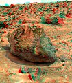
Barnacle Bill is a small rock immediately west-northwest of the Mars Pathfinder lander and was the first rock visited by the Sojourner Rover's alpha proton X-ray spectrometer (APXS) instrument. This image shows super resolution techniques applied to the first APXS target rock, which was never imaged with the rover's forward cameras. Super resolution was applied to help to address questions about the texture of this rock and what it might tell us about its mode of origin. This view of Barnacle Bill was produced by combining the "Insurance Pan" frames taken while the IMP camera was still in its stowed position on sol2. The composite color frames that make up this anaglyph were produced for both the right and left eye of the IMP. The right eye composite consists of 5 frames, taken with different color filters, the left eye consists of only 1 frame. The resultant image from each eye was enlarged by 500% and then co-added using Adobe Photoshop to produce, in effect, a super-resolution panchromatic frame that is sharper than an individual frame would be. These panchromatic frames were then colorized with the red, green, and blue filtered images from the same sequence. The color balance was adjusted to approximate the true color of Mars. The anaglyph view was produced by combining the left with the right eye color composite frames by assigning the left eye composite view to the red color plane and the right eye composite view to the green and blue color planes (cyan), to produce a stereo anaglyph mosaic. This mosaic can be viewed in 3-D on your computer monitor or in color print form by wearing red-blue 3-D glasses. Mars Pathfinder is the second in NASA's Discovery program of low-cost spacecraft with highly focused science goals. Barnacle Bill is a small rock immediately west-northwest of the Mars Pathfinder lander and was the first rock visited by the Sojourner Rover's alpha proton X-ray spectrometer (APXS) instrument.
-
Barnacle Bill is a small rock immediately west-northwest of the Mars Pathfinder lander and was the first rock visited by the Sojourner Rover's alpha proton X-ray spectrometer (APXS) instrument. This image shows super resolution techniques applied to the first APXS target rock, which was never imaged with the rover's forward cameras. Super resolution was applied to help to address questions about the texture of this rock and what it might tell us about its mode of origin. This view of Barnacle Bill was produced by combining the "Super Panorama" frames from the IMP camera. Super resolution was applied to help to address questions about the texture of these rocks and what it might tell us about their mode of origin. The composite color frames that make up this anaglyph were produced for both the right and left eye of the IMP. The composites consist of 7 frames in the right eye and 8 frames in the left eye, taken with different color filters that were enlarged by 500% and then co-added using Adobe Photoshop to produce, in effect, a super-resolution panchromatic frame that is sharper than an individual frame would be. These panchromatic frames were then colorized with the red, green, and blue filtered images from the same sequence. The color balance was adjusted to approximate the true color of Mars. The anaglyph view was produced by combining the left with the right eye color composite frames by assigning the left eye composite view to the red color plane and the right eye composite view to the green and blue color planes (cyan), to produce a stereo anaglyph mosaic. This mosaic can be viewed in 3-D on your computer monitor or in color print form by wearing red-blue 3-D glasses. Mars Pathfinder is the second in NASA's Discovery program of low-cost spacecraft with highly focused science goals. The Jet Propulsion Laboratory, Pasadena, CA, developed and manages the Mars Pathfinder mission for NASA's Office of Space Science, Washington, D.C. JPL is a division of the California Institute of Technology (Caltech) The left eye and right eye panoramas from which this anaglyph was created are available at PIA02405 andPIA02406.
-
This view of the Bookshelf Two was produced by combining the "Super Panorama" frames from the IMP camera. Super resolution was applied to help to address questions about the texture of these rocks and what it might tell us about their mode of origin. The composite color frames that make up this anaglyph were produced for both the right and left eye of the IMP. The composites consist of 7 frames in the right eye and 8 frames in the left eye, taken with different color filters that were enlarged by 500% and then co-added using Adobe Photoshop to produce, in effect, a super-resolution panchromatic frame that is sharper than an individual frame would be. These panchromatic frames were then colorized with the red, green, and blue filtered images from the same sequence. The color balance was adjusted to approximate the true color of Mars. The anaglyph view was produced by combining the left with the right eye color composite frames by assigning the left eye composite view to the red color plane and the right eye composite view to the green and blue color planes (cyan), to produce a stereo anaglyph mosaic. This mosaic can be viewed in 3-D on your computer monitor or in color print form by wearing red-blue 3-D glasses. Mars Pathfinder is the second in NASA's Discovery program of low-cost spacecraft with highly focused science goals. The Jet Propulsion Laboratory, Pasadena, CA, developed and manages the Mars Pathfinder mission for NASA's Office of Space Science, Washington, D.C. JPL is a division of the California Institute of Technology (Caltech). The left eye and right eye panoramas from which this anaglyph was created is available at PIA02405 andPIA02406
-
This view of the Boo Boo, just past Jogi to the northwest, was produced by combining the "Super Panorama" frames from the IMP camera. Super resolution was applied to help to address questions about the texture of this rock and what it might tell us about its mode of origin. The composite color frames that make up this anaglyph were produced for both the right and left eye of the IMP. The composites consist of 7 frames in the right eye and 8 frames in the left eye, taken with different color filters that were enlarged by 500% and then co-added using Adobe Photoshop to produce, in effect, a super-resolution panchromatic frame that is sharper than an individual frame would be. These panchromatic frames were then colorized with the red, green, and blue filtered images from the same sequence. The color balance was adjusted to approximate the true color of Mars. The anaglyph view was produced by combining the left with the right eye color composite frames by assigning the left eye composite view to the red color plane and the right eye composite view to the green and blue color planes (cyan), to produce a stereo anaglyph mosaic. This mosaic can be viewed in 3-D on your computer monitor or in color print form by wearing red-blue 3-D glasses. Mars Pathfinder is the second in NASA's Discovery program of low-cost spacecraft with highly focused science goals. The Jet Propulsion Laboratory, Pasadena, CA, developed and manages the Mars Pathfinder mission for NASA's Office of Space Science, Washington, D.C. JPL is a division of the California Institute of Technology (Caltech). The left eye and right eye panoramas from which this anaglyph was created is available at PIA02405 andPIA02406
-
This view of the Chimp was produced by combining the "Super Panorama" frames from the IMP camera. Super resolution was applied to help to address questions about the texture of this rock and what it might tell us about its mode of origin. The composite color frames that make up this anaglyph were produced for both the right and left eye of the IMP. These composites consist of 7 frames in the right eye and 8 frames in the left eye, taken with different color filters that were enlarged by 500% and then co-added using Adobe Photoshop to produce, in effect, a super-resolution panchromatic frame that is sharper than an individual frame would be. These panchromatic frames were then colorized with the red, green, and blue filtered images from the same sequence. The color balance was adjusted to approximate the true color of Mars. The anaglyph view was produced by combining the left with the right eye color composite frames by assigning the left eye composite view to the red color plane and the right eye composite view to the green and blue color planes (cyan), to produce a stereo anaglyph mosaic. This mosaic can be viewed in 3-D on your computer monitor or in color print form by wearing red-blue 3-D glasses. Mars Pathfinder is the second in NASA's Discovery program of low-cost spacecraft with highly focused science goals. The Jet Propulsion Laboratory, Pasadena, CA, developed and manages the Mars Pathfinder mission for NASA's Office of Space Science, Washington, D.C. JPL is a division of the California Institute of Technology (Caltech). The left eye and right eye panoramas from which this anaglyph was created is available at PIA02405 andPIA02406
-
This view of the Ender, due south of the lander, was produced by combining the "Super Panorama" frames from the IMP camera. Super resolution was applied to help to address questions about the texture of this rock and what it might tell us about its mode of origin. The composite color frames that make up this anaglyph were produced for both the right and left eye of the IMP. These composites consist of 7 frames in the right eye and 8 frames in the left eye, taken with different color filters that were enlarged by 500% and then co-added using Adobe Photoshop to produce, in effect, a super-resolution panchromatic frame that is sharper than an individual frame would be. These panchromatic frames were then colorized with the red, green, and blue filtered images from the same sequence. The color balance was adjusted to approximate the true color of Mars. The anaglyph view was produced by combining the left with the right eye color composite frames by assigning the left eye composite view to the red color plane and the right eye composite view to the green and blue color planes (cyan), to produce a stereo anaglyph mosaic. This mosaic can be viewed in 3-D on your computer monitor or in color print form by wearing red-blue 3-D glasses. Mars Pathfinder is the second in NASA's Discovery program of low-cost spacecraft with highly focused science goals. The Jet Propulsion Laboratory, Pasadena, CA, developed and manages the Mars Pathfinder mission for NASA's Office of Space Science, Washington, D.C. JPL is a division of the California Institute of Technology (Caltech). The left eye and right eye panoramas from which this anaglyph was created is available at PIA02405 andPIA02406
-
This view of the Flat Top, southwest of the lander, was produced by combining the "Super Panorama" frames from the IMP camera. Super resolution was applied to help to address questions about the texture of this rock and what it might tell us about its mode of origin. The composite color frames that make up this anaglyph were produced for both the right and left eye of the IMP. These composites consist of 7 frames in the right eye and 8 frames in the left eye, taken with different color filters that were enlarged by 500% and then co-added using Adobe Photoshop to produce, in effect, a super-resolution panchromatic frame that is sharper than an individual frame would be. These panchromatic frames were then colorized with the red, green, and blue filtered images from the same sequence. The color balance was adjusted to approximate the true color of Mars. The anaglyph view was produced by combining the left with the right eye color composite frames by assigning the left eye composite view to the red color plane and the right eye composite view to the green and blue color planes (cyan), to produce a stereo anaglyph mosaic. This mosaic can be viewed in 3-D on your computer monitor or in color print form by wearing red-blue 3-D glasses. Mars Pathfinder is the second in NASA's Discovery program of low-cost spacecraft with highly focused science goals. The Jet Propulsion Laboratory, Pasadena, CA, developed and manages the Mars Pathfinder mission for NASA's Office of Space Science, Washington, D.C. JPL is a division of the California Institute of Technology (Caltech). The left eye and right eye panoramas from which this anaglyph was created is available at PIA02405 andPIA02406
Fri May 25 13:22:15 EDT 2007
[edit]-
This view of the Flute Top was produced by combining the "Super Panorama" frames from the IMP camera. Super resolution was applied to help to address questions about the texture of this rock and what it might tell us about its mode of origin. The composite color frames that make up this anaglyph were produced for both the right and left eye of the IMP. These composites consist of 7 frames in the right eye and 8 frames in the left eye, taken with different color filters that were enlarged by 500% and then co-added using Adobe Photoshop to produce, in effect, a super-resolution panchromatic frame that is sharper than an individual frame would be. These panchromatic frames were then colorized with the red, green, and blue filtered images from the same sequence. The color balance was adjusted to approximate the true color of Mars. The anaglyph view was produced by combining the left with the right eye color composite frames by assigning the left eye composite view to the red color plane and the right eye composite view to the green and blue color planes (cyan), to produce a stereo anaglyph mosaic. This mosaic can be viewed in 3-D on your computer monitor or in color print form by wearing red-blue 3-D glasses. Mars Pathfinder is the second in NASA's Discovery program of low-cost spacecraft with highly focused science goals. The Jet Propulsion Laboratory, Pasadena, CA, developed and manages the Mars Pathfinder mission for NASA's Office of Space Science, Washington, D.C. JPL is a division of the California Institute of Technology (Caltech). The left eye and right eye panoramas from which this anaglyph was created is available at PIA02405 andPIA02406
-
This view of the Grommit was produced by combining the "Super Panorama" frames from the IMP camera. Super resolution was applied to help to address questions about the texture of this rock and what it might tell us about its mode of origin. The composite color frames that make up this anaglyph were produced for both the right and left eye of the IMP. These composites consist of 7 frames in the right eye and 8 frames in the left eye, taken with different color filters that were enlarged by 500% and then co-added using Adobe Photoshop to produce, in effect, a super-resolution panchromatic frame that is sharper than an individual frame would be. These panchromatic frames were then colorized with the red, green, and blue filtered images from the same sequence. The color balance was adjusted to approximate the true color of Mars. The anaglyph view was produced by combining the left with the right eye color composite frames by assigning the left eye composite view to the red color plane and the right eye composite view to the green and blue color planes (cyan), to produce a stereo anaglyph mosaic. This mosaic can be viewed in 3-D on your computer monitor or in color print form by wearing red-blue 3-D glasses. Mars Pathfinder is the second in NASA's Discovery program of low-cost spacecraft with highly focused science goals. The Jet Propulsion Laboratory, Pasadena, CA, developed and manages the Mars Pathfinder mission for NASA's Office of Space Science, Washington, D.C. JPL is a division of the California Institute of Technology (Caltech). The left eye and right eye panoramas from which this anaglyph was created is available at PIA02405 andPIA02406
-
This view of the Half Dome was produced by combining the "Super Panorama" frames from the IMP camera. Super resolution was applied to help to address questions about the texture of this rock and what it might tell us about its mode of origin. The composite color frames that make up this anaglyph were produced for both the right and left eye of the IMP. These composites consist of 7 frames in the right eye and 8 frames in the left eye, taken with different color filters that were enlarged by 500% and then co-added using Adobe Photoshop to produce, in effect, a super-resolution panchromatic frame that is sharper than an individual frame would be. These panchromatic frames were then colorized with the red, green, and blue filtered images from the same sequence. The color balance was adjusted to approximate the true color of Mars. The anaglyph view was produced by combining the left with the right eye color composite frames by assigning the left eye composite view to the red color plane and the right eye composite view to the green and blue color planes (cyan), to produce a stereo anaglyph mosaic. This mosaic can be viewed in 3-D on your computer monitor or in color print form by wearing red-blue 3-D glasses. Mars Pathfinder is the second in NASA's Discovery program of low-cost spacecraft with highly focused science goals. The Jet Propulsion Laboratory, Pasadena, CA, developed and manages the Mars Pathfinder mission for NASA's Office of Space Science, Washington, D.C. JPL is a division of the California Institute of Technology (Caltech). The left eye and right eye panoramas from which this anaglyph was created is available at PIA02405 andPIA02406
-
This view of the Hippo, 25 meters to the west of the lander, was produced by combining the "Super Panorama" frames from the IMP camera. Super resolution was applied to help to address questions about the texture of this rock and what it might tell us about its mode of origin. The composite color frames that make up this anaglyph were produced for both the right and left eye of the IMP. These composites consist of more than 15 frames per eye (because multiple sequences covered the same area), taken with different color filters that were enlarged by 500% and then co-added using Adobe Photoshop to produce, in effect, a super-resolution panchromatic frame that is sharper than an individual frame would be. These panchromatic frames were then colorized with the red, green, and blue filtered images from the same sequence. The color balance was adjusted to approximate the true color of Mars. The anaglyph view was produced by combining the left with the right eye color composite frames by assigning the left eye composite view to the red color plane and the right eye composite view to the green and blue color planes (cyan), to produce a stereo anaglyph mosaic. This mosaic can be viewed in 3-D on your computer monitor or in color print form by wearing red-blue 3-D glasses. Mars Pathfinder is the second in NASA's Discovery program of low-cost spacecraft with highly focused science goals. The Jet Propulsion Laboratory, Pasadena, CA, developed and manages the Mars Pathfinder mission for NASA's Office of Space Science, Washington, D.C. JPL is a division of the California Institute of Technology (Caltech). The left eye and right eye panoramas from which this anaglyph was created is available at PIA02405 andPIA02406
-
Mini Matterhorn is a 3/4 meter rock immediately east-southeast of the Mars Pathfinder lander. This view was produced by combining the "Super Panorama" frames from the IMP camera. Super resolution was applied to help to address questions about the texture of this rock and what it might tell us about its mode of origin. The composite color frames that make up this anaglyph were produced for both the right and left eye of the IMP. These composites consist of 7 frames in the right eye and 8 frames in the left eye, taken with different color filters that were enlarged by 500% and then co-added using Adobe Photoshop to produce, in effect, a super-resolution panchromatic frame that is sharper than an individual frame would be. These panchromatic frames were then colorized with the red, green, and blue filtered images from the same sequence. The color balance was adjusted to approximate the true color of Mars. The anaglyph view was produced by combining the left with the right eye color composite frames by assigning the left eye composite view to the red color plane and the right eye composite view to the green and blue color planes (cyan), to produce a stereo anaglyph mosaic. This mosaic can be viewed in 3-D on your computer monitor or in color print form by wearing red-blue 3-D glasses. Mars Pathfinder is the second in NASA's Discovery program of low-cost spacecraft with highly focused science goals. The Jet Propulsion Laboratory, Pasadena, CA, developed and manages the Mars Pathfinder mission for NASA's Office of Space Science, Washington, D.C. JPL is a division of the California Institute of Technology (Caltech). The left eye and right eye panoramas from which this anaglyph was created is available at PIA02405 andPIA02406
-
This view of Moe & Pumpkin, part of the Bookshelf at the back of the Rock Garden to the southwest of the lander, was produced by combining the "Super Panorama" frames from the IMP camera. Super resolution was applied to help to address questions about the texture of this rock and what it might tell us about its mode of origin. The composite color frames that make up this anaglyph were produced for both the right and left eye of the IMP. These composites consist of 7 frames in the right eye and 8 frames in the left eye, taken with different color filters that were enlarged by 500% and then co-added using Adobe Photoshop to produce, in effect, a super-resolution panchromatic frame that is sharper than an individual frame would be. These panchromatic frames were then colorized with the red, green, and blue filtered images from the same sequence. The color balance was adjusted to approximate the true color of Mars. The anaglyph view was produced by combining the left with the right eye color composite frames by assigning the left eye composite view to the red color plane and the right eye composite view to the green and blue color planes (cyan), to produce a stereo anaglyph mosaic. This mosaic can be viewed in 3-D on your computer monitor or in color print form by wearing red-blue 3-D glasses. Mars Pathfinder is the second in NASA's Discovery program of low-cost spacecraft with highly focused science goals. The Jet Propulsion Laboratory, Pasadena, CA, developed and manages the Mars Pathfinder mission for NASA's Office of Space Science, Washington, D.C. JPL is a division of the California Institute of Technology (Caltech). The left eye and right eye panoramas from which this anaglyph was created is available at PIA02405 andPIA02406
-
This view of Shark was produced by combining the "Super Panorama" frames from the IMP camera. Super resolution was applied to help to address questions about the texture of this rock and what it might tell us about its mode of origin. The composite color frames that make up this anaglyph were produced for both the right and left eye of the IMP. These composites consist of 7 frames in the right eye and 8 frames in the left eye, taken with different color filters that were enlarged by 500% and then co-added using Adobe Photoshop to produce, in effect, a super-resolution panchromatic frame that is sharper than an individual frame would be. These panchromatic frames were then colorized with the red, green, and blue filtered images from the same sequence. The color balance was adjusted to approximate the true color of Mars. The anaglyph view was produced by combining the left with the right eye color composite frames by assigning the left eye composite view to the red color plane and the right eye composite view to the green and blue color planes (cyan), to produce a stereo anaglyph mosaic. This mosaic can be viewed in 3-D on your computer monitor or in color print form by wearing red-blue 3-D glasses. Mars Pathfinder is the second in NASA's Discovery program of low-cost spacecraft with highly focused science goals. The Jet Propulsion Laboratory, Pasadena, CA, developed and manages the Mars Pathfinder mission for NASA's Office of Space Science, Washington, D.C. JPL is a division of the California Institute of Technology (Caltech). The left eye and right eye panoramas from which this anaglyph was created is available at PIA02405 andPIA02406
-
This view of Stimpy, in the Rock Garden, was produced by combining the "Super Panorama" frames from the IMP camera. Super resolution was applied to help to address questions about the texture of this rock and what it might tell us about its mode of origin. The composite color frames that make up this anaglyph were produced for both the right and left eye of the IMP. These composites consist of 7 frames in the right eye and 8 frames in the left eye, taken with different color filters that were enlarged by 500% and then co-added using Adobe Photoshop to produce, in effect, a super-resolution panchromatic frame that is sharper than an individual frame would be. These panchromatic frames were then colorized with the red, green, and blue filtered images from the same sequence. The color balance was adjusted to approximate the true color of Mars. The anaglyph view was produced by combining the left with the right eye color composite frames by assigning the left eye composite view to the red color plane and the right eye composite view to the green and blue color planes (cyan), to produce a stereo anaglyph mosaic. This mosaic can be viewed in 3-D on your computer monitor or in color print form by wearing red-blue 3-D glasses. Mars Pathfinder is the second in NASA's Discovery program of low-cost spacecraft with highly focused science goals. The Jet Propulsion Laboratory, Pasadena, CA, developed and manages the Mars Pathfinder mission for NASA's Office of Space Science, Washington, D.C. JPL is a division of the California Institute of Technology (Caltech). The left eye and right eye panoramas from which this anaglyph was created is available at PIA02405 andPIA02406
-
This view of Wedge was produced by combining the "Super Panorama" frames from the IMP camera. Super resolution was applied to help to address questions about the texture of this rock and what it might tell us about its mode of origin. The composite color frames that make up this anaglyph were produced for both the right and left eye of the IMP. Each composite consists of 7 frames, taken with different color filters that were enlarged by 500% and then co-added using Adobe Photoshop to produce, in effect, a super-resolution panchromatic frame that is sharper than an individual frame would be. These panchromatic frames were then colorized with the red, green, and blue filtered images from the same sequence. The color balance was adjusted to approximate the true color of Mars. The anaglyph view was produced by combining the left with the right eye color composite frames by assigning the left eye composite view to the red color plane and the right eye composite view to the green and blue color planes (cyan), to produce a stereo anaglyph mosaic. This mosaic can be viewed in 3-D on your computer monitor or in color print form by wearing red-blue 3-D glasses. Mars Pathfinder is the second in NASA's Discovery program of low-cost spacecraft with highly focused science goals. The Jet Propulsion Laboratory, Pasadena, CA, developed and manages the Mars Pathfinder mission for NASA's Office of Space Science, Washington, D.C. JPL is a division of the California Institute of Technology (Caltech). The left eye and right eye panoramas from which this anaglyph was created is available at PIA02405 andPIA02406
-
Yogi is a meter-size rock about 5 meters northwest of the Mars Pathfinder lander and was the second rock visited by the Sojourner Rover's alpha proton X-ray spectrometer (APXS) instrument. This view of was produced combining the "Super Panorama" frames from the IMP camera. Super resolution was applied to help to address questions about the texture of this rock and what it might tell us about its mode of origin. The composite color frames that make up this anaglyph were produced for both the right and left eye of the IMP (in this case, the view of Yogi is a mosaic). These composites consist of 7 frames in the right eye and 8 frames in the left eye, taken with different color filters that were enlarged by 500% and then co-added using Adobe Photoshop to produce, in effect, a super-resolution panchromatic frame that is sharper than an individual frame would be. These panchromatic frames were then colorized with the red, green, and blue filtered images from the same sequence. The color balance was adjusted to approximate the true color of Mars. The anaglyph view was produced by combining the left with the right eye color composite frames by assigning the left eye composite view to the red color plane and the right eye composite view to the green and blue color planes (cyan), to produce a stereo anaglyph mosaic. This mosaic can be viewed in 3-D on your computer monitor or in color print form by wearing red-blue 3-D glasses. Mars Pathfinder is the second in NASA's Discovery program of low-cost spacecraft with highly focused science goals. The Jet Propulsion Laboratory, Pasadena, CA, developed and manages the Mars Pathfinder mission for NASA's Office of Space Science, Washington, D.C. JPL is a division of the California Institute of Technology (Caltech). The left eye and right eye panoramas from which this anaglyph was created is available at PIA02405 andPIA02406
-
This is a more recent "geometrically improved, color enhanced" version of the 360-degree "Gallery Pan", the first contiguous, uniform panorama taken by the Imager for Mars (IMP) over the course of Sols 8, 9, and 10. Different regions were imaged at different times over the three Martian days to acquire consistent lighting and shadow conditions for all areas of the panorama. In this version of the panorama, much of the discontinuity that was due to parallax has been corrected, particularly along the lower tiers of the mosaic containing the Lander features. Distortion due to a 2.5 degree tilt in the IMP camera mast has been removed. The IMP is a stereo imaging system that, in its fully deployed configuration, stands 1.8 meters above the Martian surface, and has a resolution of two millimeters at a range of two meters. The IMP has color capability provided by 24 selectable filters -- twelve filters per "eye". Its red, green, and blue filters were used to take this panorama. The three color images were first digitally balanced according to the transmittance capabilities of a specific high-definition TV device at JPL, and then enhanced via changes to saturation and intensity while retaining the hue. A threshold was applied to avoid changes to the sky. An MTF filter was applied to sharpen feature edges. At left is a Lander petal and a metallic mast which is a portion of the low-gain antenna. On the horizon the double "Twin Peaks" are visible, about 1-2 kilometers away. The rock "Couch" is the dark, curved rock at right of Twin Peaks. Another Lander petal is at left-center, showing the fully deployed forward ramp at far left, and rear ramp at right, which rover Sojourner used to descend to the surface of Mars on July 5. Immediately to the left of the rear ramp is the rock "Barnacle Bill", which scientists found be andesitic, possibly indicating that it is a volcanic rock (a true andesite) or a physical mixture of particles. Just beyond Barnacle Bill, rover tracks lead to Sojourner, shown using its Alpha Proton X-Ray Spectrometer (APXS) instrument to study the large rock "Yogi". Yogi, low in quartz content, appears to be more primitive than Barnacle Bill, and appears more like the common basalts found on Earth. The tracks and circular pattern in the soil leading up to Yogi were part of Sojourner's soil mechanics experiments, in which varying amounts of pressure were applied to the wheels in order to determine physical properties of the soil. During its traverse to Yogi the rover stirred the soil and exposed material from several centimeters in depth. During one of the turns to deploy Sojourner's Alpha Proton X-Ray Spectrometer, the wheels dug particularly deeply and exposed white material. Spectra of this white material show it is virtually identical to the rock "Scooby Doo", and such white material may underlie much of the site. Deflated airbags are visible at the perimeter of all three Lander petals. Mars Pathfinder is the second in NASA's Discovery program of low-cost spacecraft with highly focused science goals. The Jet Propulsion Laboratory, Pasadena, CA, developed and manages the Mars Pathfinder mission for NASA's Office of Space Science, Washington, D.C. JPL is an operating division of the California Institute of Technology (Caltech). The IMP was developed by the University of Arizona Lunar and Planetary Laboratory under contract to JPL. Peter Smith is the Principal Investigator.
-
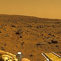
The true color of Mars based upon three filters with the sky set to aluminance of 60. The color of the Pathfinder landing site is yellowish brown with only subtle variations. These colors are identical to the measured colors of the Viking landing sites reported by Huck et al. [1977]. This image was taken near local noon on Sol 10. A description of the techniques used to generate this color image from IMP data can be found in Maki et al., 1999. Note: a calibrated output device is required accurately reproduce the correct colors. Mars Pathfinder is the second in NASA's Discovery program of low-cost spacecraft with highly focused science goals. The Jet Propulsion Laboratory, Pasadena, CA, developed and manages the Mars Pathfinder mission for NASA's Office of Space Science, Washington, D.C. JPL is an operating division of the California Institute of Technology (Caltech). The IMP was developed by the University of Arizona Lunar and Planetary Laboratory under contract to JPL. Peter Smith is the Principal Investigator.
-
Sunrise, sol 39. This true color, pre-sunrise image (approximately 0530LST) is composed of six images extending 30 ° in azimuth and 45 ° in elevation and shows the brownish gray predawn sky. A description of the techniques used to generate this color image from IMP data can be found in Maki et al., 1999. Note: a calibrated output device is required accurately reproduce the correct colors. Mars Pathfinder is the second in NASA's Discovery program of low-cost spacecraft with highly focused science goals. The Jet Propulsion Laboratory, Pasadena, CA, developed and manages the Mars Pathfinder mission for NASA's Office of Space Science, Washington, D.C. JPL is an operating division of the California Institute of Technology (Caltech). The IMP was developed by the University of Arizona Lunar and Planetary Laboratory under contract to JPL. Peter Smith is the Principal investigator.
-
Mars Pathfinder Lander camera image of Sojourner Rover atop the "Mermaid Dune' on Sol 30. Note the dark material excavated by the rover wheels. These, and other excavations brought materials to the surface for examination and allowed estimates of mechanical properties of the deposits. "Mermaid Dune" is also shown in PIA01132. This version is a mosaic of that release with data of the surrounding terrain from the Gallery panorama. Mars Pathfinder is the second in NASA's Discovery program of low-cost spacecraft with highly focused science goals. The Jet Propulsion Laboratory, Pasadena, CA, developed and manages the Mars Pathfinder mission for NASA's Office of Space Science, Washington, D.C. JPL is an operating division of the California Institute of Technology (Caltech). The IMP was developed by the University of Arizona Lunar and Planetary Laboratory under contract to JPL. Peter Smith is the Principal investigator.
-
This set of images shows the Mars Pathfinder lander in a cleanroom at JPL in 1996 on the left, and on Mars in 1997 (see PIA01238). Mars Pathfinder is the second in NASA's Discovery program of low-cost spacecraft with highly focused science goals. The Jet Propulsion Laboratory, Pasadena, CA, developed and manages the Mars Pathfinder mission for NASA's Office of Space Science, Washington, D.C. JPL is an operating division of the California Institute of Technology (Caltech). The IMP was developed by the University of Arizona Lunar and Planetary Laboratory under contract to JPL. Peter Smith is the Principal investigator.
-
This 8-image mosaic was acquired during the late afternoon (near 5pm LST, note the long shadows) on Sol 2 as part of the predeploy "insurance panorama" and shows the newly deployed rover sitting on the Martian surface. This color image was generated from images acquired at 530,600, and 750 nm. The insurance panorama was designed as "insurance" against camera failure upon deployment. Had the camera failed, the losslessly-compressed, multispectral insurance panorama would have been the main source of image data from the IMP. However, the camera deployment was successful, leaving the insurance panorama to be downlinked to Earth several weeks later. Ironically enough, the insurance panorama contains some of the best quality image data because of the lossless data compression and relatively dust-free state of the camera and associated lander/rover hardware on Sol 2. Mars Pathfinder is the second in NASA's Discovery program of low-cost spacecraft with highly focused science goals. The Jet Propulsion Laboratory, Pasadena, CA, developed and manages the Mars Pathfinder mission for NASA's Office of Space Science, Washington, D.C. JPL is an operating division of the California Institute of Technology (Caltech). The IMP was developed by the University of Arizona Lunar and Planetary Laboratory under contract to JPL. Peter Smith is the Principal investigator.
-
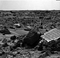
ojourner's left rear wheel is perched on the rock "Wedge" in this image, taken on Sol 47 by the Imager for Mars Pathfinder (IMP). The rover's Alpha Proton X-ray Spectrometer (APXS) is the cylindrical object extending from the back of the rover. This image and PIA01556(left eye) make up a stereo pair. Mars Pathfinder is the second in NASA's Discovery program of low-cost spacecraft with highly focused science goals. The Jet Propulsion Laboratory, Pasadena, CA, developed and manages the Mars Pathfinder mission for NASA's Office of Space Science, Washington, D.C. JPL is an operating division of the California Institute of Technology (Caltech).
-
Sojourner Rover is seen traversing near Half Dome in this image, taken on Sol 59 by the Imager for Mars Pathfinder (IMP). The rover's Alpha Proton X-ray Spectrometer (APXS) is the cylindrical object extending from the back of the rover. This image and PIA01559(right eye) make up a stereo pair. Mars Pathfinder is the second in NASA's Discovery program of low-cost spacecraft with highly focused science goals. The Jet Propulsion Laboratory, Pasadena, CA, developed and manages the Mars Pathfinder mission for NASA's Office of Space Science, Washington, D.C. JPL is an operating division of the California Institute of Technology (Caltech).
-
ojourner Rover is seen traversing near Half Dome in this image, taken on Sol 59 by the Imager for Mars Pathfinder (IMP). The rover's Alpha Proton X-ray Spectrometer (APXS) is the cylindrical object extending from the back of the rover. This image and PIA01558(left eye) make up a stereo pair. Mars Pathfinder is the second in NASA's Discovery program of low-cost spacecraft with highly focused science goals. The Jet Propulsion Laboratory, Pasadena, CA, developed and manages the Mars Pathfinder mission for NASA's Office of Space Science, Washington, D.C. JPL is an operating division of the California Institute of Technology (Caltech).
Tue May 22 22:02:55 EDT 2007
[edit]-
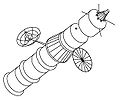
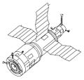
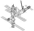
Graphic of Mir Hardware Heritage
-
Graphic of Mir Hardware Heritage
-
Graphic of Mir Hardware Heritage
-
Graphic of Mir Hardware Heritage
Tue May 22 12:15:23 EDT 2007
[edit]-
art of the constellation Scorpius centred on NGC 6357 which has star cluster Pismis 24 in its centre. This image is a colour composite taken by the Digitized Sky Survey (DSS), the field of view is 3.8x3.3 degrees.
Tue May 22 11:40:05 EDT 2007
[edit]-
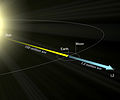
Orbit of James Webb Space Telescope
Sun May 20 17:51:02 EDT 2007
[edit]Sat May 19 00:34:53 EDT 2007
[edit]-
Figure 1-8. Original Soyuz probe and drogue docking system. The active unit (right) consisted of a probe and latches; the passive unit, a receiving cone, socket, and catches. The passive unit’s frustum was longer than the active unit’s because it was designed to accept the probe. The probe acted as a shock absorber. Its tip contained sensors which registered contact with the cone, disabled the active craft’s control system, and fired thrusters on the active craft to force the spacecraft together. The probe entered the socket at the apex of the cone, whereupon catches and a restraining ring locked it into place. Plugs and sockets in the rims of the docking units then established electrical and intercom connections between the spacecraft.21
-
Figure 1-9. L1 (Zond) circumlunar spacecraft.
-
Figure 1-10. Proton configured for= L1 (Zond). Note the modified Soyuz shroud (top).
-
Figure 1-11. L2 (Lunar Orbit Module). At the front of the spacecraft (left) is the Aktiv unit of the lunar mission Kontakt docking system.
-
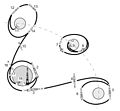
Figure 1-12. N-1/L3 lunar mission profile. 1. N-1 rocket liftoff. 2. LRS Earth orbit insertion. 3. LRS translunar injection using Block G rocket stage. Block G separates. 4. Midcourse correction using Block D rocket stage. 5. Lunar orbital insertion using Block D rocket stage. 6. Single cosmonaut transfers from L2 to L3 by EVA. 7. L3 lunar lander and Block D rocket stage separate from L2 Lunar Orbit Module. 8. Deorbit burn and powered descent using Block D rocket stage. Expended Block D rocket stage separates from the L3 1 to 3 km above the lunar surface. L3 continues powered descent using its own main or backup rocket motor. 9. L3 touchdown on Moon. 10. Expended Block D rocket stage crashes on Moon. 11. L3 liftoff using same engines used for final descent. Legs are left on Moon. 12. L2 rendezvous and docking with L3. 13. Cosmonaut transfers from L3 to L2 by EVA. L3 discarded. 14. Trans-Earth insertion burn using L2 main engine. 15. Midcourse correction using L2 main engine. 16. Orbital module and service module discarded. 17. Descent module reentry. 18. Parachute descent and touchdown on land.
-
Figure 1-13. N-1 rocket configured for lunar flight. The basic rocket consisted of the Block A first stage, the Block B second stage, and the Block V third stage. All stages burned liquid oxygen and kerosene. For lunar missions the LRS was added. The N-1 would have delivered about 100,000 kg to low-Earth orbit. (For a comparison with the U.S. Saturn V rocket, see figure 4-1).
-
Figure 1-14. Lunar rocket system. Consisted of (bottom to top) the Block G and Block D rocket stages, the L3 lander, and the L2 command ship.
-
Figure 1-15. Kontakt docking system. Never used in space, the system was designed for the Soviet lunar program. The Aktiv unit (top) was located at the front of the L2, while the passive unit was located on top of the L3 lander.
-
Figure 1-16. L3 lunar lander. The flat, downward-facing face (left) of the ovoid pressure cabin holds the round viewport (not visible). The Kontakt system passive unit is at cabin top, and two landing radar booms extend at left and right. Nozzles of two solid-fueled hold-down rockets are visible at the tops of the legs, near the bases of the radar booms.
-
Figure 1-17. L3 ascent.
-
Figure 1-18. Salyut 1-type Soyuz. This was the Original Soyuz upgraded for Salyut space stations. The probe and drogue docking system (left) permitted internal transfer of cosmonauts from the Soyuz to the station.
-
Figure 1-19. Soyuz internal transfer docking unit. This system is used today for docking spacecraft to Mir. The active craft inserts its probe into the space station receiving cone. The probe tip catches on latches in the socket at the apex of the cone. Motors then draw the two spacecraft together. Latches in the docking collars catch, and motors close them. Fluid, gas, and electrical connections are established through the collars. After the cosmonauts are certain the seal is airtight, they remove the probe and drogue units, forming a tunnel between spacecraft and station. At undocking, four spring push rods drive the spacecraft apart. If the latches fail to retract, the spacecraft can fire pyrotechnic bolts to detach from the station.
-
Figure 1-20. Soyuz Ferry.
-
Figure 1-21. Apollo-Soyuz Test Project (ASTP) Soyuz. The APAS-75 docking unit is located at left.
-
Figure 1-22. APAS-75 docking unit. Unlike previous docking systems, both units could assume the active or passive roles as required. For docking, the spade-shaped guides of the extended active unit (right) and the retracted passive unit (left) interacted for gross alignment. The ring holding the guides shifted to align the active unit latches with the passive unit catches. After these caught, shock absorbers dissipated residual impact energy in the American unit; mechanical attenuators served the same function on the the Soviet side. The active unit then retracted to bring the docking collars together. Guides and sockets in the docking collars completed alignment. Four spring push rods drove the spacecraft apart at undocking. The passive craft could play a modified active role in undocking if the active craft could not complete the standard undocking procedure. Pyrotechnic bolts provided backup.
-
Figure 1-23. Apollo and Soyuz join in space. Note the docking module (DM) attached to Apollo’s nose. The DM was stored for launch within a shroud between the CSM and the S-IVB second stage of the Apollo Saturn IB launch vehicle. In orbit the Apollo inserted its probe unit into the standard Apollo drogue unit of the docking module, extracted the DM from the S-IVB, then performed rendezvous and docking with the Soyuz spacecraft.
-
Figure 1-25. Progress-based Gamma astrophysical research satellite.
-
Figure 1-27. Ballistic return capsule (Raduga) during final descent to Earth.
-
Figure 1-28. Soyuz-T spacecraft.
-
Figure 1-29. Soyuz launch pad abort sequence. The modules of the Soyuz spacecraft are shown beneath the launch shroud by dashed lines. Note the separation plane between the Soyuz descent and service modules.
-
Figure 1-30. Soyuz-TM spacecraft. Compare the antennae on the orbital module to those on Soyuz-T. Differences reflect the change from the Igla rendezvous system used on Soyuz-T to the Kurs rendezvous system used on Soyuz-TM.
-
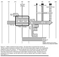
Figure 2-1. Station evolution. The chart above summarizes the development of the Soviet/Russian space stations and derivatives. Light gray arrows trace the evolution of space stations and satellites derived from space station hardware. Dark gray arrows trace the influence of concepts on later flown hardware. The stippled arrow leads from the Soyuz Programs chart (figure 1-1). Solid black arrows indicate modules joined to Mir, while dashed black arrows stand for modules to be added to Mir in the near future. These arrows lead from the Station Modules and Tug Programs chart (figure 3-1).
-
Figure 2-2. Conceptual drawing of Siber multimodule space station and Siber ferry (1962).
-
Figure 2-3. Salyut 1. Visible at the rear of the station (left) is the Soyuz-based propulsion module. A Salyut 1 Soyuz prepares to dock at the front of the station (right). Note the station’s Soyuz-type solar arrays.
-
Figure 2-4. Partial cutaway of Proton configured for space station launch. The three-stage Proton rocket has launched all Soviet space stations and space station modules. Proton first flew as a two-stage vehicle in 1965. The threestage version used to launch stations debuted in 1969 and was declared operational in 1970. All three stages burn UDMH and N2O4 propellants. The three-stage Proton can place 20,000 kg in a circular 185 km orbit at 51.6° of inclination.
-
Figure 2-5. Almaz radar satellite.
-
Figure 2-6. Conceptual drawing of Shuttle docked with Salyut.
-
Figure 2-7. Salyut 3, the first successful Almaz space station. The drogue docking unit is at the rear of the station (left), between the two main engines.
-
Figure 1-2. L1 Soyuz manned circumlunar concept (1962). Should not be confused with the L1 (Zond) spacecraft (figure 1-9). The cone at the front (right) of the L1 Soyuz is an attitude control module; behind it are cylindrical orbital and descent modules, and a frustum-shaped service module. The round appendage (right) is a solar array, and the dish, a high-gain antenna. At the rear of the L1 are three booster modules.
-
Figure 2-8. Salyut 4, the second DOS station to be manned.
-
Figure 2-9. Salyut 6, the third DOS station to be manned. Addition of the aft port (left) forced redesign of the main propulsion system.
-
Figure 2-10. Key to icons. Salyut 6 and Salyut 7 each had two docking ports; the Mir base block has two docking ports and four berthing ports. Multiple docking ports mean continual configuration changes as spacecraft come and go and modules are added. The icons shown here are combined in sections 2.7.3, 2.8.3, and 2.9.3 to depict the changing configurations of the three multimodular stations throughout their careers (1977-1994). The icons and icon combinations are strictly representative, and do not depict the true orientation of solar arrays or true relative sizes.
-
Salyut 6 September 29-October 10, 1977
-
Soyuz 25 • Salyut 6 October 10, 1977
-
Salyut 6 October 10-December 11, 1977
-
Salyut 6 • Soyuz 26 December 11, 1977-January 11, 1978
-
Soyuz 27 • Salyut 6 • Soyuz 26 January 11-16, 1978
-
Soyuz 27 • Salyut 6 • Progress 1 January 22-February 6, 1978
-
Soyuz 27 • Salyut 6 • Soyuz 28 March 3-10, 1978
-
Figure 1-3. Vostok rocket. This is a two-and-a-half-stage derivative of the one-and-ahalf-stage rocket which launched Sputnik 1 (1957). Its original ancestor was the SS-6 “Sapwood” ICBM. It served as the basis for the Soyuz launcher (figure 1-7), in service today. Weight of payload launched to 200-km, 51° circular orbit is 4730 kg.
-
Soyuz 27 • Salyut 6 March 10-16, 1978
-
Salyut 6 March 16-June 16, 1978
-
Soyuz 29 • Salyut 6 June 16-29, 1978
-
Soyuz 29 • Salyut 6 • Soyuz 30 June 29-July 5, 1978
-
Soyuz 29 • Salyut 6 • Progress 2 July 9-August 2, 1978
-
Soyuz 29 • Salyut 6 July 5-9, 1978
-
Figure 1-4. Soyuz-A manned spacecraft concept (1963). It was to have been part of the Soyuz A-B-C circumlunar complex.
-
Figure 1-5. Soyuz A-B-C circumlunar concept. The drawing shows Soyuz-A (right), Soyuz-B booster, and Soyuz-C tanker with twin whip antennae (left).
-
Figure 1-6. Original Soyuz spacecraft.
-
Figure 1-7. Soyuz rocket. With more than 1000 launches to its credit since 1963, the two-and-a-half-stage Soyuz rocket has flown more than any other. Propellants are liquid oxygen and kerosene. Weight of payload launched to 200-km, 51° circular orbit is 7000 kg.
Fri May 18 14:04:32 EDT 2007
[edit]-
Figure 1-1. Soyuz evolution. The light gray arrows trace the evolution of flown spacecraft. The dark gray arrows show influence of concepts and flown spacecraft on other concepts and flown spacecraft. Broad black lines enclose distinct programs. The stippled and light gray arrows pointing downward, off the chart, connect to the Space Station chart (figure 2-1) and the Station Modules and Tug Programs chart (figure 3-1), respectively.
Fri May 18 11:20:50 EDT 2007
[edit]-
This document was prepared by the Information Services Division, Information Systems Directorate, NASA Johnson Space Center, in response to the many requests for information on Soviet/Russian spaceflight received by the Scientific and Technical Information Center in the division’s Information Management Branch. We hope this document will be helpful to anyone interested in Soviet/Russian spaceflight. In particular, we hope it will provide new insights to persons working on the Shuttle-Mir missions and International Space Station Alpha. As a look at the sources listed at the end of each part will show, this work is based primarily on Russian sources, usually in English translation. Unfortunately, these sources often conflict. In this work preference is given to sources which contain abundant details, verifiable or otherwise; are corroborated in whole or in part by at least one other Russian source; and are the product of persons or organizations that can be expected to have intimate knowledge of the hardware and events described. This is an exciting time to study Soviet/Russian spaceflight. New light is thrown regularly on mysteries decades old. But there has not yet been time to tell all the old secrets. Because of this, new revelations still occur frequently. Most of this work will likely remain an accurate account; however, specific interpretations and details will as likely prove inaccurate as new information is revealed. So it is with any book on Soviet/Russian spaceflight written in this time of transition. Some readers may note what they perceive to be an undue emphasis on Soviet/Russian mission and hardware anomalies. This is partly a result of the document’s focus, which is, after all, on Soviet/Russian hardware history. (The reader will note that, where appropriate, U.S. anomalies are mentioned as well.) In addition, in the Soviet era, anomalies were often the chief (or only) way new information about secret hardware emerged. All countries have had their share of problems on the space frontier. Mention of anomalies in this document should not be construed as criticism of hardware or management in any country. This document is an updated and corrected edition of document JSC 26770 (October 1994). New material updates the Soyuz-TM, Progress-M, Mir Career, and Comparative Chronology sections to November 15, 1994. Sundry corrections and additions have been made at the suggestion of readers of the JSC edition or on the basis of information unavailable when the JSC edition was written. Readers should also note the addition of an index.
Fri May 18 11:03:24 EDT 2007
[edit]-
Mir from Page one of the Mir Hardware Heritage
-
This document was prepared by the Information Services Division, Information Systems Directorate, NASA Johnson Space Center, in response to the many requests for information on Soviet/Russian spaceflight received by the Scientific and Technical Information Center in the division’s Information Management Branch. We hope this document will be helpful to anyone interested in Soviet/Russian spaceflight. In particular, we hope it will provide new insights to persons working on the Shuttle-Mir missions and International Space Station Alpha. As a look at the sources listed at the end of each part will show, this work is based primarily on Russian sources, usually in English translation. Unfortunately, these sources often conflict. In this work preference is given to sources which contain abundant details, verifiable or otherwise; are corroborated in whole or in part by at least one other Russian source; and are the product of persons or organizations that can be expected to have intimate knowledge of the hardware and events described. This is an exciting time to study Soviet/Russian spaceflight. New light is thrown regularly on mysteries decades old. But there has not yet been time to tell all the old secrets. Because of this, new revelations still occur frequently. Most of this work will likely remain an accurate account; however, specific interpretations and details will as likely prove inaccurate as new information is revealed. So it is with any book on Soviet/Russian spaceflight written in this time of transition. Some readers may note what they perceive to be an undue emphasis on Soviet/Russian mission and hardware anomalies. This is partly a result of the document’s focus, which is, after all, on Soviet/Russian hardware history. (The reader will note that, where appropriate, U.S. anomalies are mentioned as well.) In addition, in the Soviet era, anomalies were often the chief (or only) way new information about secret hardware emerged. All countries have had their share of problems on the space frontier. Mention of anomalies in this document should not be construed as criticism of hardware or management in any country. This document is an updated and corrected edition of document JSC 26770 (October 1994). New material updates the Soyuz-TM, Progress-M, Mir Career, and Comparative Chronology sections to November 15, 1994. Sundry corrections and additions have been made at the suggestion of readers of the JSC edition or on the basis of information unavailable when the JSC edition was written. Readers should also note the addition of an index.
Fri May 18 11:02:34 EDT 2007
[edit]-
NASA Logo from Page 1 of the Mir Hardware Heritage.
Thu May 17 12:00:53 EDT 2007
[edit]-
This high-resolution image captured by the Mars Exploration Rover Opportunity's panoramic camera highlights the puzzling rock outcropping that scientists are eagerly planning to investigate. Presently, Opportunity is on its lander facing northeast; the outcropping lies to the northwest. These layered rocks measure only 10 centimeters (4 inches) tall and are thought to be either volcanic ash deposits or sediments carried by water or wind. Data from the panoramic camera's near-infrared, blue and green filters were combined to create this approximate, true-color image. The Outcrop in a Nutshell Figure 1 highlights various rock targets within the outcrop lining the inner edge of the small crater where the rover landed. Opportunity recently finished examining the rock dubbed "Last Chance," then rolled over to "Wave Ripple," a section of rock in the region nicknamed "The Dells." Tomorrow, March 6, 2004, Sol 41, the rover will take a series of "touch-and-go" microscopic images at "Wave Ripple," before heading to another rock region with targets named "Slick Rock" and "Berry Bowl."
Thu May 17 11:48:53 EDT 2007
[edit]-
The First IMP Image from Mars Acquired by the Mars Pathfinder Imager on 8:42 MLST sol1.
-
This is the first image captured by the Imager for Mars Pathfinder (IMP)that dedicates a significant portion of the frame to the Martian surface. This image was acquired by IMP at 8:48 MLST sol 1.
-
This Imager for Mars Pathfinder (IMP) image shows the Sojourner latch spring before (left image) and after (right image) deployment. This is how visual confirmation was made that at least one side of the rover had stood up and locked in place as planned.
-
These stills are from the first rover movie which showed the rover being deployed and touching down on the Martian surface.
-
This illustration is a composite that creatively combines two previously released images from Mars Pathfinder for a sunset scene in Ares Valles in July 1997. The combined images are PIA01547 for the sky, and a portion of PIA01466 for the terrain. The sky image is a radiometrically correct, true-color sunset, with the sky near the Sun a pale blue color. The terrain image has been artistically adjusted to match the approximate time of day of the sky image (4:10 p.m. local solar time at the landing site) and to provide a seamless horizon. The two source images are composites of several frames from the Imager for Mars Pathfinder camera. Additional information is available in the captions for the original images.
Thu May 17 11:41:58 EDT 2007
[edit]-
Tracks made by the Sojourner rover are visible in this image, taken by one of the cameras aboard Sojourner on Sol 3. The tracks represent the rover maneuvering towards the rock dubbed "Barnacle Bill." The rover, having exited the lander via the rear ramp, first traveled towards the right portion of the image, and then moved forward towards the left where Barnacle Bill sits. The fact that the rover was making defined tracks indicates that the soil is made up of particles on a micron scale. Mars Pathfinder was developed and managed by the Jet Propulsion Laboratory (JPL) for the National Aeronautics and Space Administration.
-
This is one of the first images taken by one of the three Sojourner rover cameras on Sol 3. At right, portions of the lander's deflated airbags and circular high-gain antenna are visible. The Martian horizon is at the background. Sojourner is equipped with three cameras -- a forward stereo system and rear color imaging system. These imaging systems will be used over the course of the rover's mission to get close-up views of rocks and soil. Mars Pathfinder is the second in NASA's Discovery program of low-cost spacecraft with highly focused science goals. The Jet Propulsion Laboratory, Pasadena, CA, developed and manages the Mars Pathfinder mission for NASA's Office of Space Science, Washington, D.C.
-
Portions of Sojourner's Alpha Proton X-Ray Spectrometer (APXS), a deployment spring, and the rock Barnacle Bill are visible in this color image. The image was taken by Sojourner's rear camera, and shows that the APXS made good contact with Barnacle Bill. Mars Pathfinder is the second in NASA's Discovery program of low-cost spacecraft with highly focused science goals. The Jet Propulsion Laboratory, Pasadena, CA, developed and manages the Mars Pathfinder mission for NASA's Office of Space Science, Washington, D.C. JPL is an operating division of the California Institute of Technology (Caltech). The Imager for Mars Pathfinder (IMP) was developed by the University of Arizona Lunar and Planetary Laboratory under contract to JPL. Peter Smith is the Principal Investigator.
-
The image was taken by a camera aboard the Sojourner rover on Sol 4. The large rock Yogi can be seen at the upper right portion of the image. Sojourner's Alpha Proton X-Ray Spectrometer instrument is currently studying the sand around Yogi, and may study Yogi itself later on. Mars Pathfinder is the second in NASA's Discovery program of low-cost spacecraft with highly focused science goals. The Jet Propulsion Laboratory, Pasadena, CA, developed and manages the Mars Pathfinder mission for NASA's Office of Space Science, Washington, D.C. JPL is an operating division of the California Institute of Technology (Caltech). The Imager for Mars Pathfinder (IMP) was developed by the University of Arizona Lunar and Planetary Laboratory under contract to JPL. Peter Smith is the Principal Investigator.
-
The image was taken by a camera aboard the Sojourner rover on Sol 4. The large rock Yogi can be seen at the upper right portion of the image. Sojourner's Alpha Proton X-Ray Spectrometer instrument is currently studying the sand around Yogi, and may study Yogi itself later on. One of Sojourner's cleated wheels is visible at lower right. Mars Pathfinder is the second in NASA's Discovery program of low-cost spacecraft with highly focused science goals. The Jet Propulsion Laboratory, Pasadena, CA, developed and manages the Mars Pathfinder mission for NASA's Office of Space Science, Washington, D.C. JPL is an operating division of the California Institute of Technology (Caltech). The Imager for Mars Pathfinder (IMP) was developed by the University of Arizona Lunar and Planetary Laboratory under contract to JPL. Peter Smith is the Principal Investigator.
-
The image was taken by a camera aboard the Sojourner rover on Sol 4. Portions of the rover's Alpha Proton X-Ray Spectrometer (APXS) instrument are visible studying Barnacle Bill. Mars Pathfinder is the second in NASA's Discovery program of low-cost spacecraft with highly focused science goals. The Jet Propulsion Laboratory, Pasadena, CA, developed and manages the Mars Pathfinder mission for NASA's Office of Space Science, Washington, D.C. JPL is an operating division of the California Institute of Technology (Caltech).
-
The image was taken by a camera aboard the Sojourner rover on Sol 4. A rover wheel is at center, and tracks are visible in the soil at top where the cleated wheel passed over the surface. Mars Pathfinder is the second in NASA's Discovery program of low-cost spacecraft with highly focused science goals. The Jet Propulsion Laboratory, Pasadena, CA, developed and manages the Mars Pathfinder mission for NASA's Office of Space Science, Washington, D.C. JPL is an operating division of the California Institute of Technology (Caltech).
Thu May 17 11:38:25 EDT 2007
[edit]-
Taken from Sojourner's front stereo camera, this image features the large rock Yogi and hole dug by the front wheel of the rover into the Martian soil. The rover is maneuvering into a position better suited to image Yogi's intriguing features. Mars Pathfinder is the second in NASA's Discovery program of low-cost spacecraft with highly focused science goals. The Jet Propulsion Laboratory, Pasadena, CA, developed and manages the Mars Pathfinder mission for NASA's Office of Space Science, Washington, D.C. JPL is an operating division of the California Institute of Technology (Caltech). The Imager for Mars Pathfinder (IMP) was developed by the University of Arizona Lunar and Planetary Laboratory under contract to JPL. Peter Smith is the Principal Investigator.
-
Taken from Sojourner's forward camera, this image features a rover's-eye view of the Sagan Memorial Station. Areas of billowing airbags can be seen surrounding the lander, and the rear deployment ramp is seen at center. The rock Barnacle Bill is just to the right of the ramp, and Sojourner's tracks are shown leading away from the spacecraft. The lander's high-gain antenna is at the left of the lander's main electronics array, appearing as a small grey disc. Mars Pathfinder is the second in NASA's Discovery program of low-cost spacecraft with highly focused science goals. The Jet Propulsion Laboratory, Pasadena, CA, developed and manages the Mars Pathfinder mission for NASA's Office of Space Science, Washington, D.C. JPL is an operating division of the California Institute of Technology (Caltech). The Imager for Mars Pathfinder (IMP) was developed by the University of Arizona Lunar and Planetary Laboratory under contract to JPL. Peter Smith is the Principal Investigator.
-
This view from the Sojourner rover's rear color camera shows wheel tracks in the orange-red martian soil. One of the rover's cleated wheels is visible at left. Mars Pathfinder is the second in NASA's Discovery program of low-cost spacecraft with highly focused science goals. The Jet Propulsion Laboratory, Pasadena, CA, developed and manages the Mars Pathfinder mission for NASA's Office of Space Science, Washington, D.C. JPL is an operating division of the California Institute of Technology (Caltech).
-
This view from the Sojourner rover's rear color camera shows a close-up view of the large rock nicknamed "Yogi." Mars Pathfinder is the second in NASA's Discovery program of low-cost spacecraft with highly focused science goals. The Jet Propulsion Laboratory, Pasadena, CA, developed and manages the Mars Pathfinder mission for NASA's Office of Space Science, Washington, D.C. JPL is an operating division of the California Institute of Technology (Caltech).
-
One of Sojourner's two front cameras took this image of the Sagan Memorial Station on Sol 6. The lander and its deployed rear ramp are at upper left, while several large rocks appear at center. Sojourner was near the large rock Yogi when this image was taken. Mars Pathfinder is the second in NASA's Discovery program of low-cost spacecraft with highly focused science goals. The Jet Propulsion Laboratory, Pasadena, CA, developed and manages the Mars Pathfinder mission for NASA's Office of Space Science, Washington, D.C. JPL is an operating division of the California Institute of Technology (Caltech). The Imager for Mars Pathfinder (IMP) was developed by the University of Arizona Lunar and Planetary Laboratory under contract to JPL. Peter Smith is the Principal Investigator.
-
One of the two forward cameras aboard the Sojourner rover took this image of the Sagan Memorial Station on Sol 25. The camera uses a fisheye lens which produces the illumination gradient in the sky on the western horizon. The angular resolution of the camera is about three milliradians (.018 degrees) per pixel, which is why the image appears grainy. Features seen on the lander include (from left to right): the Atmospheric Structure Instrument / Meteorology Package (ASI/MET) mast with windsocks; the low-gain antenna mast, the Imager for Mars Pathfinder (IMP) on its mast at center; the disc-shaped high-gain antenna at right, and areas of deflated airbags. The dark circle on the lander body is a filtered vent that allowed air to escape during launch, and allowed the lander to repressurize upon landing. The high-gain antenna is pointed at Earth. The large rock Yogi, which Sojourner has approached and studied, is at the far right of the image. Mars Pathfinder is the second in NASA's Discovery program of low-cost spacecraft with highly focused science goals. The Jet Propulsion Laboratory, Pasadena, CA, developed and manages and Mars Pathfinder mission for NASA's Office of Space Science, Washington, D.C. JPL is an operating division of the California Institute of Technology (Caltech). The Imager for Mars Pathfinder (IMP) was developed by the University of Arizona Lunar and Planetary Laboratory under contract to JPL. Peter Smith is the Principal Investigator.
-
One of the two forward cameras aboard Sojourner imaged this area of Martian terrain on Sol 26. The large rock dubbed "Pooh Bear" is at far left, and stands between four and five inches high. Mermaid Dune is the smooth area stretching horizontally across the top quarter of the image. The Alpha Proton X-Ray Spectrometer (APXS) instrument aboard Sojourner will be deployed on Mermaid Dune, and the rover will later use its cleated wheels to dig into it. Mars Pathfinder is the second in NASA's Discovery program of low-cost spacecraft with highly focused science goals. The Jet Propulsion Laboratory, Pasadena, CA, developed and manages and Mars Pathfinder mission for NASA's Office of Space Science, Washington, D.C. JPL is an operating division of the California Institute of Technology (Caltech). The Imager for Mars Pathfinder (IMP) was developed by the University of Arizona Lunar and Planetary Laboratory under contract to JPL. Peter Smith is the Principal Investigator.
-
One of the two forward cameras aboard the Sojourner rover took this image of the Sagan Memorial Station on Sol 26. The angular resolution of the camera is about three milliradians (.018 degrees) per pixel, which is why the image appears grainy. The field of view of each rover camera is about 127 degrees horizontally and 90 degrees vertically. Features seen on the lander include (from left to right): the Atmospheric Structure Instrument/Meteorology Package (ASI/MET) mast with windsocks; the low-gain antenna mast, the Imager for Mars Pathfinder (IMP) on its mast at center; the disc-shaped high-gain antenna at right, and areas of deflated airbags. The dark circle on the lander body is a filtered vent that allowed air to escape during launch, and allowed the lander to repressurize upon landing. The high-gain antenna is pointed at Earth. The large rock Yogi, which Sojourner has approached and studied, as at the far right of the image. Mini Matterhorn is the large rock situated in front of the lander at left. The horizontal line at the center of the image is due to differences in light-metering for different portions of the image. The shadow of Sojourner and its antenna are visible at the lower section of the image. The antenna's shadow falls across a light-colored rock. Mars Pathfinder is the second in NASA's Discovery program of low-cost spacecraft with highly focused science goals. The Jet Propulsion Laboratory, Pasadena, CA, developed and manages and Mars Pathfinder mission for NASA's Office of Space Science, Washington, D.C. JPL is an operating division of the California Institute of Technology (Caltech). The Imager for Mars Pathfinder (IMP) was developed by the University of Arizona Lunar and Planetary Laboratory under contract to JPL. Peter Smith is the Principal Investigator.
-
This image was taken by the Sojourner rover's left front camera on Sol 32. The Pathfinder lander is at right and is about 9 meters away. Wind tails of dust are clearly seen extending from the left side of many of the small rocks in the foreground. The large rocks on the horizon at left center are the next goal of Sojourner as it continues our exploration of Mars. Mars Pathfinder is the second in NASA's Discovery program of low-cost spacecraft with highly focused science goals. The Jet Propulsion Laboratory, Pasadena, CA, developed and managed the Mars Pathfinder mission for NASA's Office of Space Science, Washington, D.C. JPL is a division of the California Institute of Technology (Caltech).
-
This image from the Sojourner rover's right front camera was taken on Sol 27. The Pathfinder lander is seen at middle left. The large rock at right, nicknamed "Squash", exhibits a diversity of textures. It looks very similar to a conglomerate, a type of rock found on Earth that forms from sedimentary processes. Mars Pathfinder is the second in NASA's Discovery program of low-cost spacecraft with highly focused science goals. The Jet Propulsion Laboratory, Pasadena, CA, developed and managed the Mars Pathfinder mission for NASA's Office of Space Science, Washington, D.C. JPL is a division of the California Institute of Technology (Caltech).
Thu May 17 11:32:22 EDT 2007
[edit]-
This image was taken by the Sojourner rover's right front camera on Sol 33. The rock in the foreground, nicknamed "Ender", is pitted and marked by a subtle horizontal texture. The bright material on the top of the rock is probably wind-deposited dust. The Pathfinder Lander is seen in the distance at right. The lander camera is the cylindrical object on top of the deployed mast. Mars Pathfinder is the second in NASA's Discovery program of low-cost spacecraft with highly focused science goals. The Jet Propulsion Laboratory, Pasadena, CA, developed and managed the Mars Pathfinder mission for NASA's Office of Space Science, Washington, D.C. JPL is a division of the California Institute of Technology (Caltech).
-
The front cameras aboard the rover Sojourner imaged several prominent rocks on Sol 44. The highly-textured rock at left is Wedge, and in the background from left to right are Shark, Half-Dome, and Moe. The rectangular rock at right is Flat Top, which earlier close-up images revealed to be made up of elongated pits, possibly made by vesicles from volcanic outgassing or etches caused by weathering. Mars Pathfinder is the second in NASA's Discovery program of low-cost spacecraft with highly focused science goals. The Jet Propulsion Laboratory, Pasadena, CA, developed and manages the Mars Pathfinder mission for NASA's Office of Space Science, Washington, D.C. JPL is a division of the California Institute of Technology (Caltech).
-
This mosaic of the Mars Pathfinder lander and Martian terrain was taken by the front camera on the Sojourner rover on Sol 39. The rover, positioned near the rock "Wedge" at left, has imaged the letters "JPL" and the American flag mounted on the side of the lander's electronics box. A large spread of deflated airbags are strewn around the lander's periphery, and the large rock Yogi, studied earlier in the mission by Sojourner's Alpha Proton X-Ray Spectrometer instrument, lies behind the airbags in the background. The front rover deployment ramp is at right, while the Imager for Mars Pathfinder mounted on its mast stands high at the top of the lander's electronics box. Mars Pathfinder is the second in NASA's Discovery program of low-cost spacecraft with highly focused science goals. The Jet Propulsion Laboratory, Pasadena, CA, developed and manages the Mars Pathfinder mission for NASA's Office of Space Science, Washington, D.C. JPL is a division of the California Institute of Technology (Caltech).
-
This image of the rock "Wedge" was taken from the Sojourner rover's rear color camera on Sol 37. The position of the rover relative to Wedge is seen in MRPS 83349. The segmented rod visible in the middle of the frame is the deployment arm for the Alpha Proton X-Ray Spectrometer (APXS). The APXS, the bright, cylindrical object at the end of the arm, is positioned against Wedge and is designed to measure the rock's chemical composition. This was done successfully on the night of Sol 37. Mars Pathfinder is the second in NASA's Discovery program of low-cost spacecraft with highly focused science goals. The Jet Propulsion Laboratory, Pasadena, CA, developed and manages the Mars Pathfinder mission for NASA's Office of Space Science, Washington, D.C. JPL is a division of the California Institute of Technology (Caltech). The Imager for Mars Pathfinder (IMP) was developed by the University of Arizona Lunar and Planetary Laboratory under contract to JPL. Peter Smith is the Principal Investigator.
-
This image of the rock "Flat Top" was taken from one of the Sojourner rover's front cameras on Sol 42. Pits on the edge of the rock and a fluted surface are clearly visible. The rocks in the left background comprise the Rock Garden. Mars Pathfinder is the second in NASA's Discovery program of low-cost spacecraft with highly focused science goals. The Jet Propulsion Laboratory, Pasadena, CA, developed and manages the Mars Pathfinder mission for NASA's Office of Space Science, Washington, D.C. JPL is a division of the California Institute of Technology (Caltech).
-
The Sojourner rover's front right camera imaged Pop-tart, a small rock or indurated soil material which was pushed out of the surrounding drift material by Sojourner's front left wheel during a soil mechanics experiment. Mars Pathfinder is the second in NASA's Discovery program of low-cost spacecraft with highly focused science goals. The Jet Propulsion Laboratory, Pasadena, CA, developed and manages the Mars Pathfinder mission for NASA's Office of Space Science, Washington, D.C. JPL is a division of the California Institute of Technology (Caltech). The Imager for Mars Pathfinder (IMP) was developed by the University of Arizona Lunar and Planetary Laboratory under contract to JPL. Peter Smith is the Principal Investigator.
-
This image, taken by Sojourner's front right camera, was taken when the rover was next to Poohbear (rock at left) and Piglet (not seen) as it looked out toward Mermaid Dune. The textures differ from the foreground soil containing a sorted mix of small rocks, fines and clods, from the area a bit ahead of the rover where the surface is covered with a bright drift material. Soil experiments where the rover wheels dug in the soil revealed that the cloudy material exists underneath the drift. Mars Pathfinder is the second in NASA's Discovery program of low-cost spacecraft with highly focused science goals. The Jet Propulsion Laboratory, Pasadena, CA, developed and manages the Mars Pathfinder mission for NASA's Office of Space Science, Washington, D.C. JPL is a division of the California Institute of Technology (Caltech).
-
This view of the rock "Chimp" was acquired by the Sojourner rover's right front camera on Sol 74 (September 17). A large crack, oriented from lower left to upper right, is visible in the rock. A dark crust appears to cover Chimp in some areas whereas other parts of the rock have a lighter shading. A boundary between the two regions is clearly seen in the upper left part of Chimp. Mars Pathfinder is the second in NASA's Discovery program of low-cost spacecraft with highly focused science goals. The Jet Propulsion Laboratory, Pasadena, CA, developed and manages the Mars Pathfinder mission for NASA's Office of Space Science, Washington, D.C. JPL is a division of the California Institute of Technology (Caltech).
-
This image mosaic of part of the "Rock Garden" was taken by the Sojourner rover's left front camera on Sol 71 (September 14). The rock "Shark" is at left center and "Half Dome" is at right. Fine-scale textures on the rocks are clearly seen. Broken crust-like material is visible at bottom center. Mars Pathfinder is the second in NASA's Discovery program of low-cost spacecraft with highly focused science goals. The Jet Propulsion Laboratory, Pasadena, CA, developed and manages the Mars Pathfinder mission for NASA's Office of Space Science, Washington, D.C. JPL is a division of the California Institute of Technology (Caltech).
-
This stereo image pair of the rock "Chimp" was taken by the Sojourner rover's front cameras on Sol 72 (September 15). Fine-scale texture on Chimp and other rocks is clearly visible. Wind tails, oriented from lower right to upper left, are seen next to small pebbles in the foreground. These were most likely produced by wind action. Mars Pathfinder is the second in NASA's Discovery program of low-cost spacecraft with highly focused science goals. The Jet Propulsion Laboratory, Pasadena, CA, developed and manages the Mars Pathfinder mission for NASA's Office of Space Science, Washington, D.C. JPL is a division of the California Institute of Technology (Caltech).
Thu May 17 11:27:05 EDT 2007
[edit]-
A close-up view of the rock "Moe" in the Rock Garden at the Pathfinder landing site. Moe is a meter-size boulder that, as seen from Sojourner, has a relatively smooth yet pitted texture upon close examination. Such a texture is seen on Earth on rocks that have been abraded by wind in a process that is analogous to sand blasting. This view of Moe shows two faces on the rock, one (left side of the rock) facing north-northeast and the other (right side) facing east. These two faces are thought to have been pitted and fluted by strong, "sand"- carrying winds from the northeast. Mars Pathfinder is the second in NASA's Discovery program of low-cost spacecraft with highly focused science goals. The Jet Propulsion Laboratory, Pasadena, CA, developed and manages the Mars Pathfinder mission for NASA's Office of Space Science, Washington, D.C. JPL is a division of the California Institute of Technology (Caltech).
-
This image of the rock "Half Dome" was taken by the Sojourner rover's left front camera on Sol 71 (September 14). Pits, linear textures, and pronounced topography on the rock are clearly visible. Mars Pathfinder is the second in NASA's Discovery program of low-cost spacecraft with highly focused science goals. The Jet Propulsion Laboratory, Pasadena, CA, developed and manages the Mars Pathfinder mission for NASA's Office of Space Science, Washington, D.C. JPL is a division of the California Institute of Technology (Caltech).
-
This image of the rock "Chimp" was taken by the Sojourner rover's right front camera on Sol 72 (September 15). Fine-scale texture on Chimp and other rocks is clearly visible. Wind tails, oriented from lower right to upper left, are seen next to small pebbles in the foreground. These were most likely produced by wind action. Mars Pathfinder is the second in NASA's Discovery program of low-cost spacecraft with highly focused science goals. The Jet Propulsion Laboratory, Pasadena, CA, developed and manages the Mars Pathfinder mission for NASA's Office of Space Science, Washington, D.C. JPL is a division of the California Institute of Technology (Caltech).
-
This image taken on Sol 74 ( September 17) from the Sojourner rover's right front camera shows areas of the Pathfinder landing site never before seen. The shadow of the rover and its antenna is visible in the foreground. On the horizon at right are the Twin Peaks, about 1 kilometer away. Mars Pathfinder is the second in NASA's Discovery program of low-cost spacecraft with highly focused science goals. The Jet Propulsion Laboratory, Pasadena, CA, developed and manages the Mars Pathfinder mission for NASA's Office of Space Science, Washington, D.C. JPL is a division of the California Institute of Technology (Caltech).
-
This is the right image of a stereo pair taken by the Sojourner rover in the area behind the "Rock Garden" at the Pathfinder landing site and gives a view of the Martian surface not seen from the lander. Of note here are several dune-like ridges in the foreground. These features are less than a meter high but several meters wide. They are thought to be created by surface winds blowing right to left (approximately northeast to southwest). These features are called dunes, because of their asymmetry, although the rover has not examined the sediment within them. Such sediment on Earth would be sand-size grains less than 1 millimeter in diameter.
-
This pair of images shows a broad view (upper image) and detailed close-up view (lower image) of the disturbed surface near and on Mermaid Dune. Seen slightly right of center in the upper image are two diggings by the rover's wheel. The uppermost rut is in the surface away from Mermaid and is considered to be typical of the surface at the landing site. The closer rut represents the surface at the base of Mermaid on the upwind side. The lower image is an enlargement of the disturbed Mermaid sediments plus those of the underlying substrate; that is, the ground upon which the dune lies. Seen in the close-up are at least two types of sediment, one that seems to be approximately 1.4 cm thick and forms piles with sides sloping at approximately 35 degrees, and another at least 3 cm deep composed of sediment that has a characteristic slope of 41 degrees when piled. It is apparent in the images that there is a size range of sediment present in the rut, sediment that ranges from a few millimeters in size down to below the resolution of the camera. Mars Pathfinder is the second in NASA's Discovery program of low-cost spacecraft with highly focused science goals. The Jet Propulsion Laboratory, Pasadena, CA, developed and manages the Mars Pathfinder mission for NASA's Office of Space Science, Washington, D.C. JPL is a division of the California Institute of Technology (Caltech).
-
The rock "Stimpy" is seen in this close-up image taken by the Sojourner rover's left front camera on Sol 70 (September 13). Detailed texture on the rock, such as pits and flutes, are clearly visible. Mars Pathfinder is the second in NASA's Discovery program of low-cost spacecraft with highly focused science goals. The Jet Propulsion Laboratory, Pasadena, CA, developed and manages the Mars Pathfinder mission for NASA's Office of Space Science, Washington, D.C. JPL is a division of the California Institute of Technology (Caltech).
-
This Sojourner rover image of the Cabbage Patch shows small rounded objects on the surface that are about 3-4 cm across. Some of these are within excavations, which are about 0.5 cm wide. Several questions arise about the pebbles: Why are they rounded? Where did they come from? What do they mean? Geologists use MULTIPLE WORKING HYPOTHESES when attempting to explain observations. Some hypotheses that could account for the pebbles are: 1. They were rounded during transport by waters of catastrophic floods and deposited on the Ares Vallis floodplain 2. They were rounded by wave action on an ancient Martian beach 3. They were rounded during glacial transport 4. They are glasses that were produced by melting during impact cratering. The glass was first ejected from the crater, then molded into spherical shapes or drops as it traveled through the atmosphere, and finally was deposited at the sites 5. They are spatter from lava flows 6. They are nodules brought up from the deep Martian interior by lava flows or pyroclastic eruptions. 7. They are concretions formed in sedimentary rocks 8. They came from ancient conglomerate rocks. The pebbles were rounded by water action and subsequently lithified into conglomerate rocks. Later, the waters of catastrophic floods transported the conglomerates and deposited them on the Ares floodplain. The pebbles were then freed from the rocks by weathering. 9. A combination of the above Mars Pathfinder is the second in NASA's Discovery program of low-cost spacecraft with highly focused science goals. The Jet Propulsion Laboratory, Pasadena, CA, developed and manages the Mars Pathfinder mission for NASA's Office of Space Science, Washington, D.C. JPL is a division of the California Institute of Technology (Caltech).
-
This Rover image of "Shark" (upper left center), "Half Dome" (upper right), and a small rock (right foreground) reveal textures and structures not visible in lander camera images. These rocks are interpreted as conglomerates because their surfaces have rounded protrusions up to several centimeters in size. It is suggested that the protrusions are pebbles and granules. Mars Pathfinder is the second in NASA's Discovery program of low-cost spacecraft with highly focused science goals. The Jet Propulsion Laboratory, Pasadena, CA, developed and manages the Mars Pathfinder mission for NASA's Office of Space Science, Washington, D.C. JPL is a division of the California Institute of Technology (Caltech).
-
This close-up Sojourner rover image of a small rock shows that weathering has etched-out pebbles to produce sockets. In the image, sunlight is coming from the upper left. Sockets (with shadows on top) are visible at the lower left and pebbles (with bright tops and shadowed bases) are seen at the lower center and lower right. Two pebbles (about 0.5 cm across) are visible at the lower center. Mars Pathfinder is the second in NASA's Discovery program of low-cost spacecraft with highly focused science goals. The Jet Propulsion Laboratory, Pasadena, CA, developed and manages the Mars Pathfinder mission for NASA's Office of Space Science, Washington, D.C. JPL is a division of the California Institute of Technology (Caltech).
Thu May 17 11:21:27 EDT 2007
[edit]-
This Sojourner image, taken on Sol 70, shows rocks and rover-disturbed soil. Cleats on Sojourner's left front wheel are seen at lower left. The large rock in the distance is "Yogi." Much of Yogi visible in this image cannot be seen from the perspective of the Pathfinder lander. Mars Pathfinder is the second in NASA's Discovery program of low-cost spacecraft with highly focused science goals. The Jet Propulsion Laboratory, Pasadena, CA, developed and manages the Mars Pathfinder mission for NASA's Office of Space Science, Washington, D.C. JPL is a division of the California Institute of Technology (Caltech).
-
Image of Pathfinder Lander on Mars taken from Sojourner Rover left front camera on sol 33. The IMP (on the lattice mast) is looking at the rover. Airbags are prominent, and the meteorology mast is shown to the right. Lowermost rock is Ender, with Hassock behind it and Yogi on the other side of the lander. NOTE: original caption as published in Science Magazine
-
Sojourner Rover image of rounded 4-cm-wide pebble (lower center) and excavation of cloddy deposit of Cabbage Patch at lower left. Note the bright wind tails of drift material extending from small rocks and the wheel track from upper right to lower left. Well-rounded objects, like the one in this image, were not seen at the Viking sites. These are thought to be pebbles liberated from sedimentary rocks composed of cemented silts, sands and rounded fragments; such rocks are called conglomerates. NOTE: original caption as published in Science Magazine Mars Pathfinder is the second in NASA's Discovery program of low-cost spacecraft with highly focused science goals. The Jet Propulsion Laboratory, Pasadena, CA, developed and manages the Mars Pathfinder mission for NASA's Office of Space Science, Washington, D.C. JPL is a division of the California Institute of Technology (Caltech).
-
The rounded knobs (arrows) up to 3 or 4 cm wide on Shark (left; approximately 70 cm wide)) and Half Dome (upper right) and in the foreground could be pebbles in a cemented matrix of clays, silts, and sands; such rocks are called conglomerates. Well-rounded objects like these were not seen at the Viking sites. NOTE: original caption as published in Science Magazine. Mars Pathfinder is the second in NASA's Discovery program of low-cost spacecraft with highly focused science goals. The Jet Propulsion Laboratory, Pasadena, CA, developed and manages the Mars Pathfinder mission for NASA's Office of Space Science, Washington, D.C. JPL is a division of the California Institute of Technology (Caltech).
-
Well-rounded objects, like the ones in this image, were not seen at the Viking sites. These are thought to be pebbles liberated from sedimentary rocks composed of cemented silts, sands and rounded fragments; such rocks are called conglomerates. The "sockets" could be the former sites of such pebbles. NOTE: original caption as published in Science Magazine Mars Pathfinder is the second in NASA's Discovery program of low-cost spacecraft with highly focused science goals. The Jet Propulsion Laboratory, Pasadena, CA, developed and manages the Mars Pathfinder mission for NASA's Office of Space Science, Washington, D.C. JPL is a division of the California Institute of Technology (Caltech).
-
Sojourner's observations in the Ares region on Mars raise and answer questions about the origins of the rocks and other deposits found there. This image shows the vesicular and pitted textures of Souffle Rock (32 cm wide) which could be a result of volcanic, sedimentary, or weathering processes. NOTE: original caption as published in Science Magazine Mars Pathfinder is the second in NASA's Discovery program of low-cost spacecraft with highly focused science goals. The Jet Propulsion Laboratory, Pasadena, CA, developed and manages the Mars Pathfinder mission for NASA's Office of Space Science, Washington, D.C. JPL is a division of the California Institute of Technology (Caltech).
-
Sojourner's observations in the Ares region on Mars raise and answer questions about the origins of the rocks and other deposits found there. Deposits are not the same everywhere. In compressible soil, a rover wheel produced ruts with steep walls, marginal slumps, and nearly perfect reflective casts of the spacing between the cleats. NOTE: original caption as published in Science Magazine Mars Pathfinder is the second in NASA's Discovery program of low-cost spacecraft with highly focused science goals. The Jet Propulsion Laboratory, Pasadena, CA, developed and manages the Mars Pathfinder mission for NASA's Office of Space Science, Washington, D.C. JPL is a division of the California Institute of Technology (Caltech).
-
Sojourner's observations in the Ares region on Mars raise and answer questions about the origins of the rocks and other deposits found there. Deposits are not the same everywhere. Bright, fine-grained drifts (right center) are abundant as thin (less than a few centimeters), discontinuous ridged sheets and wind tails that overlie cloddy deposits of dust, clods, and tiny (less than 1 cm) rocks. NOTE: original caption as published in Science Magazine Mars Pathfinder is the second in NASA's Discovery program of low-cost spacecraft with highly focused science goals. The Jet Propulsion Laboratory, Pasadena, CA, developed and manages the Mars Pathfinder mission for NASA's Office of Space Science, Washington, D.C. JPL is a division of the California Institute of Technology (Caltech).
-
Sojourner's excavations brought materials to the surface for examination and allowed estimates of the mechanical properties of the deposits. This image is of a 7 cm wide excavation through the veneer of a drift. The platy fragment or piece of crust (upper right) was displaced by the rover wheel. NOTE: original caption as published in Science Magazine Mars Pathfinder is the second in NASA's Discovery program of low-cost spacecraft with highly focused science goals. The Jet Propulsion Laboratory, Pasadena, CA, developed and manages the Mars Pathfinder mission for NASA's Office of Space Science, Washington, D.C. JPL is a division of the California Institute of Technology (Caltech).
-
This figure contains an azimuth-elevation projection of the "Gallery Panorama." The original Simple Cylindrical mosaic has been reprojected to the inside of a sphere so that lines of constant azimuth radiate from the center and lines of constant elevation are concentric circles. This projection preserves the resolution of the original panorama. Overlaid onto the projected Martian surface is a delineation of the Sojourner rover traverse path during the 83 Sols (Martian days) of Pathfinder surface operations. The rover path was reproduced using IMP camera "end of day" and "Rover movie" image sequences and rover vehicle telemetry data as references.
Thu May 17 11:15:09 EDT 2007
[edit]-
This anaglyph view of Chimp, south southwest of the lander, was produced by combining two right eye frames taken from different viewing angles by Sojourner Rover. One of the right eye frames was distorted using Photoshop to approximate the projection of the left eye view (without this, the stereo pair is painful to view). The left view is assigned to the red color plane and the right view to the green and blue color planes (cyan), to produce a stereo anaglyph mosaic. This mosaic can be viewed in 3-D on your computer monitor or in color print form by wearing red-blue 3-D glasses. Mars Pathfinder is the second in NASA's Discovery program of low-cost spacecraft with highly focused science goals. The Jet Propulsion Laboratory, Pasadena, CA, developed and manages the Mars Pathfinder mission for NASA's Office of Space Science, Washington, D.C. JPL is a division of the California Institute of Technology (Caltech).
Thu May 17 11:12:39 EDT 2007
[edit]errors
[edit]- Image:PIA01412.jpg UnexpectedAnswerException unexpected response data (SimpleAction) status HTTP/1.0 200 OK
-
This anaglyph view of Chimp, south southwest of the lander, was produced by combining two right eye frames taken from different viewing angles by Sojourner Rover. One of the right eye frames was distorted using Photoshop to approximate the projection of the left eye view (without this, the stereo pair is painful to view). The left view is assigned to the red color plane and the right view to the green and blue color planes (cyan), to produce a stereo anaglyph mosaic. This mosaic can be viewed in 3-D on your computer monitor or in color print form by wearing red-blue 3-D glasses. Mars Pathfinder is the second in NASA's Discovery program of low-cost spacecraft with highly focused science goals. The Jet Propulsion Laboratory, Pasadena, CA, developed and manages the Mars Pathfinder mission for NASA's Office of Space Science, Washington, D.C. JPL is a division of the California Institute of Technology (Caltech).
-
These anaglyph views of Ender, due south of the lander, were produced by combining left and right views from the IMP (left image) and two right eye frames taken from different viewing angles from the rover (right image). For the rover, one of the right eye frames was distorted using Photoshop to approximate the projection of the left eye view (without this, the stereo pair is painful to view). Then, for both the lander and rover, the left view is assigned to the red color plane and the right view to the green and blue color planes (cyan), to produce a stereo anaglyph mosaic. This mosaic can be viewed in 3-D on your computer monitor or in color print form by wearing red-blue 3-D glasses. Mars Pathfinder is the second in NASA's Discovery program of low-cost spacecraft with highly focused science goals. The Jet Propulsion Laboratory, Pasadena, CA, developed and manages the Mars Pathfinder mission for NASA's Office of Space Science, Washington, D.C. JPL is a division of the California Institute of Technology (Caltech).
-
This anaglyph view of Flat Top, southwest of the lander, was produced by combining two right eye frames taken from different viewing angles by Sojourner Rover. One of the right eye frames was distorted using Photoshop to approximate the projection of the left eye view (without this, the stereo pair is painful to view). The left view is assigned to the red color plane and the right view to the green and blue color planes (cyan), to produce a stereo anaglyph mosaic. This mosaic can be viewed in 3-D on your computer monitor or in color print form by wearing red-blue 3-D glasses. Mars Pathfinder is the second in NASA's Discovery program of low-cost spacecraft with highly focused science goals. The Jet Propulsion Laboratory, Pasadena, CA, developed and manages the Mars Pathfinder mission for NASA's Office of Space Science, Washington, D.C. JPL is a division of the California Institute of Technology (Caltech).
-
This Sojourner rover panorama from Sols 75 and 76 is the only true panorama product (as opposed to the normal "tiled" full frames) produced by the rover. This panorama ranges from Big Crater on the left (about azimuth 160 degrees), past the Twin Peaks and almost all the way to the north horizon, for a swath of about 200 degrees in azimuth. Mars Pathfinder is the second in NASA's Discovery program of low-cost spacecraft with highly focused science goals. The Jet Propulsion Laboratory, Pasadena, CA, developed and manages the Mars Pathfinder mission for NASA's Office of Space Science, Washington, D.C. JPL is a division of the California Institute of Technology (Caltech).
-
This close-up image of Shark, in the Bookshelf at the back of the Rock Garden, was taken by Sojourner Rover on Sol 75. Also in the image are Half Dome (right) and Desert Princess (lower right). At the bottom left, a thin "crusty" soil layer has been disturbed by the rover wheels. Mars Pathfinder is the second in NASA's Discovery program of low-cost spacecraft with highly focused science goals. The Jet Propulsion Laboratory, Pasadena, CA, developed and manages the Mars Pathfinder mission for NASA's Office of Space Science, Washington, D.C. JPL is a division of the California Institute of Technology (Caltech).
-
This anaglyph view of Souffle, to the left of Yogi, was produced by combining two right eye frames taken from different viewing angles by Sojourner Rover on Sol 21. One of the right eye frames was distorted using Photoshop to approximate the projection of the left eye view (without this, the stereo pair is painful to view). The left view is assigned to the red color plane and the right view to the green and blue color planes (cyan), to produce a stereo anaglyph mosaic. This mosaic can be viewed in 3-D on your computer monitor or in color print form by wearing red-blue 3-D glasses. Mars Pathfinder is the second in NASA's Discovery program of low-cost spacecraft with highly focused science goals. The Jet Propulsion Laboratory, Pasadena, CA, developed and manages the Mars Pathfinder mission for NASA's Office of Space Science, Washington, D.C. JPL is a division of the California Institute of Technology (Caltech).
-
The left of the two forward cameras aboard Sojourner imaged this area of Martian terrain on Sol 26. The large rock dubbed "Pooh Bear" is at far left, and stands between four and five inches high. Mermaid Dune is the smooth area stretching horizontally across the top quarter of the image. The Alpha Proton X-Ray Spectrometer (APXS) instrument aboard Sojourner will be deployed on Mermaid Dune, and the rover will later use its cleated wheels to dig into it. This image and PIA01553(right eye) make up a stereo pair. Mars Pathfinder is the second in NASA's Discovery program of low-cost spacecraft with highly focused science goals. The Jet Propulsion Laboratory, Pasadena, CA, developed and manages the Mars Pathfinder mission for NASA's Office of Space Science, Washington, D.C. JPL is an operating division of the California Institute of Technology (Caltech). The IMP was developed by the University of Arizona Lunar and Planetary Laboratory under contract to JPL. Peter Smith is the Principal investigator.
-
The right of the two forward cameras aboard Sojourner imaged this area of Martian terrain on Sol 26. The large rock dubbed "Pooh Bear" is at far left, and stands between four and five inches high. Mermaid Dune is the smooth area stretching horizontally across the top quarter of the image. The Alpha Proton X-Ray Spectrometer (APXS) instrument aboard Sojourner will be deployed on Mermaid Dune, and the rover will later use its cleated wheels to dig into it. This image and PIA01552(left eye) make up a stereo pair. Mars Pathfinder is the second in NASA's Discovery program of low-cost spacecraft with highly focused science goals. The Jet Propulsion Laboratory, Pasadena, CA, developed and manages the Mars Pathfinder mission for NASA's Office of Space Science, Washington, D.C. JPL is an operating division of the California Institute of Technology (Caltech). The IMP was developed by the University of Arizona Lunar and Planetary Laboratory under contract to JPL. Peter Smith is the Principal investigator.
-
This image of the rock "Flat Top" was taken from the left of the Sojourner rover's front cameras on Sol 42. Pits on the edge of the rock and a fluted surface are clearly visible. The rocks in the left background comprise the Rock Garden. This image and PIA01555(right eye) make up a stereo pair. Mars Pathfinder is the second in NASA's Discovery program of low-cost spacecraft with highly focused science goals. The Jet Propulsion Laboratory, Pasadena, CA, developed and manages the Mars Pathfinder mission for NASA's Office of Space Science, Washington, D.C. JPL is an operating division of the California Institute of Technology (Caltech).
-
This image of the rock "Flat Top" was taken from the right of the Sojourner rover's front cameras on Sol 42. Pits on the edge of the rock and a fluted surface are clearly visible. The rocks in the left background comprise the Rock Garden. This image and PIA01554(left eye) make up a stereo pair. Mars Pathfinder is the second in NASA's Discovery program of low-cost spacecraft with highly focused science goals. The Jet Propulsion Laboratory, Pasadena, CA, developed and manages the Mars Pathfinder mission for NASA's Office of Space Science, Washington, D.C. JPL is an operating division of the California Institute of Technology (Caltech).
Thu May 17 11:05:02 EDT 2007
[edit]-
Sojourner's left rear wheel is perched on the rock "Wedge" in this image, taken on Sol 47 by the Imager for Mars Pathfinder (IMP). The rover's Alpha Proton X-ray Spectrometer (APXS) is the cylindrical object extending from the back of the rover. This image and PIA01557(right eye) make up a stereo pair. Mars Pathfinder is the second in NASA's Discovery program of low-cost spacecraft with highly focused science goals. The Jet Propulsion Laboratory, Pasadena, CA, developed and manages the Mars Pathfinder mission for NASA's Office of Space Science, Washington, D.C. JPL is an operating division of the California Institute of Technology (Caltech).
-
A close-up view of the rock "Moe" in the Rock Garden at the Pathfinder landing site. Moe is a meter-size boulder that, as seen from Sojourner, has a relatively smooth yet pitted texture upon close examination. Such a texture is seen on Earth on rocks that have been abraded by wind in a process that is analogous to sand blasting. This view of Moe shows two faces on the rock, one (left side of the rock) facing north-northeast and the other (right side) facing east. These two faces are thought to have been pitted and fluted by strong, "sand"- carrying winds from the northeast. This image and PIA01565(right eye) make up a stereo pair. Mars Pathfinder is the second in NASA's Discovery program of low-cost spacecraft with highly focused science goals. The Jet Propulsion Laboratory, Pasadena, CA, developed and manages the Mars Pathfinder mission for NASA's Office of Space Science, Washington, D.C. JPL is an operating division of the California Institute of Technology (Caltech).
-
A close-up view of the rock "Moe" in the Rock Garden at the Pathfinder landing site. Moe is a meter-size boulder that, as seen from Sojourner, has a relatively smooth yet pitted texture upon close examination. Such a texture is seen on Earth on rocks that have been abraded by wind in a process that is analogous to sand blasting. This view of Moe shows two faces on the rock, one (left side of the rock) facing north-northeast and the other (right side) facing east. These two faces are thought to have been pitted and fluted by strong, "sand"- carrying winds from the northeast. This image and PIA01564(left eye) make up a stereo pair. Mars Pathfinder is the second in NASA's Discovery program of low-cost spacecraft with highly focused science goals. The Jet Propulsion Laboratory, Pasadena, CA, developed and manages the Mars Pathfinder mission for NASA's Office of Space Science, Washington, D.C. JPL is an operating division of the California Institute of Technology (Caltech).
-
This image of the rock "Half Dome" was taken by the Sojourner rover's left front camera on Sol 71 (September 14). Pits, linear textures, and pronounced topography on the rock are clearly visible. This image and PIA01567(right eye) make up a stereo pair. Mars Pathfinder is the second in NASA's Discovery program of low-cost spacecraft with highly focused science goals. The Jet Propulsion Laboratory, Pasadena, CA, developed and manages the Mars Pathfinder mission for NASA's Office of Space Science, Washington, D.C. JPL is an operating division of the California Institute of Technology (Caltech).
-
This image of the rock "Half Dome" was taken by the Sojourner rover's right front camera on Sol 71 (September 14). Pits, linear textures, and pronounced topography on the rock are clearly visible. This image and PIA01566(left eye) make up a stereo pair. Mars Pathfinder is the second in NASA's Discovery program of low-cost spacecraft with highly focused science goals. The Jet Propulsion Laboratory, Pasadena, CA, developed and manages the Mars Pathfinder mission for NASA's Office of Space Science, Washington, D.C. JPL is an operating division of the California Institute of Technology (Caltech).
-
The rock "Stimpy" is seen in this close-up image taken by the Sojourner rover's left front camera on Sol 70 (September 13). Detailed texture on the rock, such as pits and flutes, are clearly visible. This image and PIA01571(right eye) make up a stereo pair. Mars Pathfinder is the second in NASA's Discovery program of low-cost spacecraft with highly focused science goals. The Jet Propulsion Laboratory, Pasadena, CA, developed and manages the Mars Pathfinder mission for NASA's Office of Space Science, Washington, D.C. JPL is an operating division of the California Institute of Technology (Caltech).
-
The rock "Stimpy" is seen in this close-up image taken by the Sojourner rover's right front camera on Sol 70 (September 13). Detailed texture on the rock, such as pits and flutes, are clearly visible. This image and PIA01570(left eye) make up a stereo pair. Mars Pathfinder is the second in NASA's Discovery program of low-cost spacecraft with highly focused science goals. The Jet Propulsion Laboratory, Pasadena, CA, developed and manages the Mars Pathfinder mission for NASA's Office of Space Science, Washington, D.C. JPL is an operating division of the California Institute of Technology (Caltech).
-
This left image of a stereo image pair of the rock "Chimp" was taken by the Sojourner rover's front cameras on Sol 72 (September 15). Fine-scale texture on Chimp and other rocks is clearly visible. Wind tails, oriented from lower right to upper left, are seen next to small pebbles in the foreground. These were most likely produced by wind action. This image and PIA01575(right eye) make up a stereo pair. Mars Pathfinder is the second in NASA's Discovery program of low-cost spacecraft with highly focused science goals. The Jet Propulsion Laboratory, Pasadena, CA, developed and manages the Mars Pathfinder mission for NASA's Office of Space Science, Washington, D.C. JPL is an operating division of the California Institute of Technology (Caltech).
-
This right image of a stereo image pair of the rock "Chimp" was taken by the Sojourner rover's front cameras on Sol 72 (September 15). Fine-scale texture on Chimp and other rocks is clearly visible. Wind tails, oriented from lower right to upper left, are seen next to small pebbles in the foreground. These were most likely produced by wind action. This image and PIA01574(left eye) make up a stereo pair. Mars Pathfinder is the second in NASA's Discovery program of low-cost spacecraft with highly focused science goals. The Jet Propulsion Laboratory, Pasadena, CA, developed and manages the Mars Pathfinder mission for NASA's Office of Space Science, Washington, D.C. JPL is an operating division of the California Institute of Technology (Caltech).
-
This right image of a stereo image pair, taken on Sol 72 (September 15) from the Sojourner rover's front cameras, shows areas of the Pathfinder landing site never before seen. The large rock on the right is "Chimp." This image and PIA01576(left eye) make up a stereo pair. Mars Pathfinder is the second in NASA's Discovery program of low-cost spacecraft with highly focused science goals. The Jet Propulsion Laboratory, Pasadena, CA, developed and manages the Mars Pathfinder mission for NASA's Office of Space Science, Washington, D.C. JPL is an operating division of the California Institute of Technology (Caltech).
Thu May 17 10:57:55 EDT 2007
[edit]-
This left image of a stereo image pair, taken on Sol 72 (September 15) from the Sojourner rover's front cameras, shows areas of the Pathfinder landing site never before seen. The large rock on the right is "Chimp." This image and PIA01577(right eye) make up a stereo pair. Mars Pathfinder is the second in NASA's Discovery program of low-cost spacecraft with highly focused science goals. The Jet Propulsion Laboratory, Pasadena, CA, developed and manages the Mars Pathfinder mission for NASA's Office of Space Science, Washington, D.C. JPL is an operating division of the California Institute of Technology (Caltech).
-
This view of the rock "Chimp" was acquired by the Sojourner rover's right front camera on Sol 74 (September 17). A large crack, oriented from lower left to upper right, is visible in the rock. A dark crust appears to cover Chimp in some areas whereas other parts of the rock have a lighter shading. A boundary between the two regions is clearly seen in the upper left part of Chimp. This image and PIA01578(left eye) make up a stereo pair. Mars Pathfinder is the second in NASA's Discovery program of low-cost spacecraft with highly focused science goals. The Jet Propulsion Laboratory, Pasadena, CA, developed and manages the Mars Pathfinder mission for NASA's Office of Space Science, Washington, D.C. JPL is an operating division of the California Institute of Technology (Caltech).
-
This image was taken by the Sojourner rover in the area behind the "Rock Garden" at the Pathfinder landing site and gives a view of the Martian surface not seen from the lander. Of note here are several dune-like ridges in the foreground. These features are less than a meter high but several meters wide. They are thought to be created by surface winds blowing right to left (approximately northeast to southwest). These features are called dunes, because of their asymmetry, although the rover has not examined the sediment within them. Such sediment on Earth would be sand-size grains less than 1 millimeter in diameter. This image and PIA00965(right eye) make up a stereo pair. Mars Pathfinder is the second in NASA's Discovery program of low-cost spacecraft with highly focused science goals. The Jet Propulsion Laboratory, Pasadena, CA, developed and manages the Mars Pathfinder mission for NASA's Office of Space Science, Washington, D.C. JPL is an operating division of the California Institute of Technology (Caltech).
-
Marie Curie rover drives down the rear ramp during Operational Readiness Test (ORT) 4. Pathfinder, a low-cost Discovery mission, is the first of a new fleet of spacecraft that are planned to explore Mars over thenext ten years. Mars Global Surveyor, already en route, arrives at Mars on September 11 to begin a two year orbital reconnaissance of the planet's composition, topography, and climate. Additional orbiters and landers will follow every 26 months. The Jet Propulsion Laboratory, Pasadena, CA, developed and manages the Mars Pathfinder mission for NASA's Office of Space Science, Washington, D.C. JPL is an operating division of the California Institute of Technology (Caltech). The Imager for Mars Pathfinder (IMP) was developed by the University of Arizona Lunar and Planetary Laboratory under contract to JPL. Peter Smith is the Principal Investigator.
-
These images are views of the Mars Pathfinder Lander's forward ramp before (top image) and after (bottom image) deployment. Some data from the before image was lost due to rover-lander communication problems.
-
This image of the Mars Pathfinder Lander on the surface of Mars was imaged by Sojourner as it looks back. Sojourners tracks are visible in the foreground
-
Sojourner takes a picture of one of its hazard-detecting laser stripes which is clearly visible against the Martian surface.
-
During a soil mechanics experiment, the rover does a wheelie, lifting its front left wheel into the air.
-
This set of images from NASA's 1997 Pathfinder mission highlight the dust devils that gust across the surface of Mars. The right image shows the dusty martian sky as our eye would see it. The left image has been enhanced to expose the dust devils that lurk in the hazy sky.
Thu May 17 10:57:08 EDT 2007
[edit]-
This view of the rock "Chimp" was acquired by the Sojourner rover's left front camera on Sol 74 (September 17). A large crack, oriented from lower left to upper right, is visible in the rock. A dark crust appears to cover Chimp in some areas whereas other parts of the rock have a lighter shading. A boundary between the two regions is clearly seen in the upper left part of Chimp. This image and PIA01579(right eye) make up a stereo pair. Mars Pathfinder is the second in NASA's Discovery program of low-cost spacecraft with highly focused science goals. The Jet Propulsion Laboratory, Pasadena, CA, developed and manages the Mars Pathfinder mission for NASA's Office of Space Science, Washington, D.C. JPL is an operating division of the California Institute of Technology (Caltech).
Wed May 16 22:10:18 EDT 2007
[edit]-
This rich galaxy cluster, catalogued as Cl 0024+17, is allowing astronomers to probe the distribution of dark matter in space. The blue streaks near the center of the image are the smeared images of very distant galaxies that are not part of the cluster. The distant galaxies appear distorted because their light is being bent and magnified by the powerful gravity of Cl 0024+17, an effect called gravitational lensing. Dark matter cannot be seen because it does not shine or reflect light. Astronomers can only detect its influence by how its gravity affects light. By mapping the distorted light created by gravitational lensing, astronomers can trace how dark matter is distributed in the cluster. While mapping the dark matter, astronomers found a dark-matter ring near the cluster's center. The ring's discovery is among the strongest evidence that dark matter exists. The Hubble observations were taken in November 2004 by the Advanced Camera for Surveys.
Wed May 16 21:36:54 EDT 2007
[edit]-
Astronomers using NASA's Hubble Space Telescope have discovered a ghostly ring of dark matter that formed long ago during a titanic collision between two massive galaxy clusters. The ring's discovery is among the strongest evidence yet that dark matter exists. Astronomers have long suspected the existence of the invisible substance as the source of additional gravity that holds together galaxy clusters. Such clusters would fly apart if they relied only on the gravity from their visible stars. Although astronomers don't know what dark matter is made of, they hypothesize that it is a type of elementary particle that pervades the universe. This Hubble composite image shows the ring of dark matter in the galaxy cluster Cl 0024+17. The ring-like structure is evident in the blue map of the cluster's dark matter distribution. The map was derived from Hubble observations of how the gravity of the cluster Cl 0024+17 distorts the light of more distant galaxies, an optical illusion called gravitational lensing. Although astronomers cannot see dark matter, they can infer its existence by mapping the distorted shapes of the background galaxies. The map is superimposed on a Hubble Advanced Camera for Surveys image of the cluster taken in November 2004.
Wed May 16 00:01:22 EDT 2007
[edit]-
Ultraviolet image of the large face on spiral galaxy NGC 3344. The inner spiral arms are wrapped so tightly that they are difficult to distinguish.
Tue May 15 23:55:20 EDT 2007
[edit]-
Ultraviolet image of the globular cluster NGC 1851 in the southern constellation Columba.
Tue May 15 22:22:04 EDT 2007
[edit]-
The two images on the left hand side of this composite image frame were taken 914 seconds and 932 seconds after the recent Deep Space 1 (DS1)encounter with the asteroid 9969 Braille by the Miniature Integrated Camera Spectrometer (MICAS). The image on the right was created by combining the two images on the left. The Sun is illuminating Braille from below , as is indicated by the arrow. Braille (also known as 1992 KD) was discovered on May 27, 1992 by astronomers Eleanor Helin and Kenneth Lawrence using the 46 centimeter (18 inch) Shmidt telescope at Palomar Observatory, while scanning the skies as part of the Palomar Planet-Crossing Asteroid Survey. Deep Space 1 was launched into orbit around the Sun on October 24, 1998 at 5:08 a.m. Pacific Daylight Time from Cape Canaveral Air Station, Florida on a Delta 7326, a variant of the Delta II rocket. An ion engine, operating for more than 1800 hours, was used to maneuver the spacecraft for an encounter with Braille. The closest approach of DS1 to the asteroid, at an approximate distance of 15 kilometers, occurred on July 29,1999 at 04:45 Universal Time, July 28 at 9:46 p.m. Pacific Daylight Time.
-
This image was created from a composite of two images which were taken 914 seconds and 932 seconds after the recent Deep Space 1 (DS1) encounter with the asteroid 9969 Braille by the Miniature Integrated Camera Spectrometer (MICAS). Interpolated values were then computed for each pixel in the final image based on the neighboring pixels of the composite. The interpolation minimizes the spatial frequency artifacts of the final image. The Sun is illuminating Braille from below. Braille (also known as 1992 KD) was discovered on May 27, 1992 by astronomers Eleanor Helin and Kenneth Lawrence using the 46 centimeter (18 inch) Shmidt telescope at Palomar Observatory, while scanning the skies as part of the Palomar Planet-Crossing Asteroid Survey. Deep Space 1 was launched into orbit around the Sun on October 24, 1998 at 5:08 a.m. Pacific Daylight Time from Cape Canaveral Air Station, Florida on a Delta 7326, a variant of the Delta II rocket. An ion engine, operating for more than 1800 hours, was used to maneuver the spacecraft for an encounter with Braille. The closest approach of DS1 to the asteroid, at an approximate distance of 15 kilometers, occurred on July 29,1999 at 04:45 Universal Time, July 28 at 9:46 p.m. Pacific Daylight Time.
-
This image, taken by Deep Space 1 on September 22, 2001, has been enhanced to reveal dust being ejected from the nucleus of comet Borrelly. As a result, the nucleus, which is about eight kilometers (about five miles) long, is bright white in the image. The main dust jet is directed towards the bottom left of the frame, around 35 degrees away from the comet-Sun line. The jet emerges as actually comprised of at least three smaller features. This active region as a whole is at least three kilometers (less than two miles) long. Another, smaller, jet feature is seen on the tip of the nucleus on the lower right-hand limb. Dust also seems to be ejected from there into the night-side hemisphere, probably from the dayside hemisphere. The expansion of the gas and dust mixture into the vacuum of space has swept some material around the body of the nucleus so that it appears above the night-side hemisphere. The night-side of the nucleus could not be seen, of course. The line between day and night on the comet is towards the upper right. This representation shows a faint ring of brightness separated from the terminator by a dark, unlit area. It is possible that this is a crater rim, seen in grazing illumination, which is just about to cross into darkness as the comet rotates. The direction to the Sun is directly downwards. Deep Space 1 completed its primary mission testing ion propulsion and 11 other advanced, high-risk technologies in September 1999. NASA extended the mission, taking advantage of the ion propulsion and other systems to undertake this chancy but exciting, and ultimately successful, encounter with the comet. More information can be found on the Deep Space 1 home page at http://nmp.jpl.nasa.gov/ds1/ . Deep Space 1 was launched in October 1998 as part of NASA's New Millennium Program, which is managed by JPL for NASA's Office of Space Science, Washington, D.C. The California Institute of Technology manages JPL for NASA.
-
Over 1300 energy spectra taken on September 22, 2001 from the ion and electron instruments on NASA's Deep Space 1 span a region of 1,400,000 kilometers (870,000 miles) centered on the closest approach to the nucleus of comet Borrelly. A very strong interaction occurs between the solar wind (horizontal red bands to left and right in figure) and the comet's surrounding cloud of dust and gas, the coma. Near Deep Space 1's closest approach to the nucleus, the solar wind picked up charged water molecules from the coma (upper green band near the center), slowing the wind sharply and creating the V-shaped energy structure at the center. Deep Space 1 completed its primary mission testing ion propulsion and 11 other advanced, high-risk technologies in September 1999. NASA extended the mission, taking advantage of the ion propulsion and other systems to undertake this chancy but exciting, and ultimately successful, encounter with the comet. More information can be found on the Deep Space 1 home page at http://nmp.jpl.nasa.gov/ds1/ . Deep Space 1 was launched in October 1998 as part of NASA's New Millennium Program, which is managed by JPL for NASA's Office of Space Science, Washington, D.C. The California Institute of Technology manages JPL for NASA.
-
Deep Space 1 flew by comet Borrelly on September 22, 2001 and took these measurements with its plasma instruments between 90,000 kilometers (56,000 miles) and 2,000 kilometers (1,200 miles) away. These data show that the flow of ions around the comet's rocky, icy nucleus (the center of the deep V-shaped feature) is not centered on the comet's nucleus as scientists expected before the Borrelly flyby. Ions in the turbulent flow are heated to about 1 million Kelvin (2 million degrees Fahrenheit) causing the bands of ions to appear broad and jagged compared to the solar wind. Deep Space 1 completed its primary mission testing ion propulsion and 11 other advanced, high-risk technologies in September 1999. NASA extended the mission, taking advantage of the ion propulsion and other systems to undertake this chancy but exciting, and ultimately successful, encounter with the comet. More information can be found on the Deep Space 1 home page at http://nmp.jpl.nasa.gov/ds1/ . Deep Space 1 was launched in October 1998 as part of NASA's New Millennium Program, which is managed by JPL for NASA's Office of Space Science, Washington, D.C. The California Institute of Technology manages JPL for NASA.
-
In this Deep Space 1 image of comet Borrelly, sunlight illuminates the bowling-pin shaped nucleus from directly below. At this distance, many features are become vivid on the surface of the nucleus, including a jagged line between day and night on the comet, rugged terrain on both ends with dark patches, and smooth, brighter terrain near the center. The smallest discernable features are about 110 meters (120 yards) across. Deep Space 1 completed its primary mission testing ion propulsion and 11 other advanced, high-risk technologies in September 1999. NASA extended the mission, taking advantage of the ion propulsion and other systems to undertake this chancy but exciting, and ultimately successful, encounter with the comet. More information can be found on the Deep Space 1 home page at http://nmp.jpl.nasa.gov/ds1/ . Deep Space 1 was launched in October 1998 as part of NASA's New Millennium Program, which is managed by JPL for NASA's Office of Space Science, Washington, D.C. The California Institute of Technology manages JPL for NASA.
-
This very long exposure was taken by NASA's Deep Space 1 to show detailed structures in the faint parts of comet Borrelly's inner coma. As a result, the nucleus has been greatly over-exposed and its shape appears distorted. The main jet extends to the lower right about 30 degrees off the Sun-line. Faint structures in the coma stretch from the nucleus in all directions. The surface of Borrelly is composed of a mixture of dust and water ice, and as the comet approaches the Sun the ice sublimes. Dust carried outward by expanding gas makes the jets visible. Deep Space 1 completed its primary mission testing ion propulsion and 11 other advanced, high-risk technologies in September 1999. NASA extended the mission, taking advantage of the ion propulsion and other systems to undertake this chancy but exciting, and ultimately successful, encounter with the comet. More information can be found on the Deep Space 1 home page at http://nmp.jpl.nasa.gov/ds1/ . Deep Space 1 was launched in October 1998 as part of NASA's New Millennium Program, which is managed by JPL for NASA's Office of Space Science, Washington, D.C. The California Institute of Technology manages JPL for NASA.
-
The solid nucleus of comet Borrelly is barely resolved in this image, enhanced to reveal the highly collimated dust extending towards the bottom left corner of the picture. The jet is attributed to dust carried outward by gas expanding outwards into a cone about 20 degrees across. The surface of Borrelly is composed of a mixture of dust and water ice, and as the comet approaches the Sun the water ice sublimes. The gases produced inside the comet by the Sun's heating race away from the surface into the vacuum of space, carrying the dust away with them. The jet was also seen in images acquired around 9 hours earlier. This suggests that the emission is coming from close to the rotation axis at the comet's constantly illuminated pole. The Sun is at the bottom of the image. Deep Space 1 completed its primary mission testing ion propulsion and 11 other advanced, high-risk technologies in September 1999. NASA extended the mission, taking advantage of the ion propulsion and other systems to undertake this chancy but exciting, and ultimately successful, encounter with the comet. More information can be found on the Deep Space 1 home page at http://nmp.jpl.nasa.gov/ds1/ . Deep Space 1 was launched in October 1998 as part of NASA's New Millennium Program, which is managed by JPL for NASA's Office of Space Science, Washington, D.C. The California Institute of Technology manages JPL for NASA.
-
A composite of images from NASA's Deep Space 1 spacecraft shows features of comet Borrelly's nucleus, dust jets escaping the nucleus and the cloud-like "coma" of dust and gases surrounding the nucleus. False color is used to reveal details of the jets and coma. The images were taken when Deep Space 1 was about 4,800 kilometers (3,000 miles) from Borrelly during a Sept. 22, 2001, flyby. Borrelly's nucleus is about 8 kilometers (5 miles) from end to end, so the field of view is about 40 kilometers (25 miles) across. The Sun shines from the bottom of the image. The main dust jet, seen extending toward the bottom left, heads away from the comet in a direction that is about 30 degrees off the direction straight toward the Sun from the comet. The colors show about three orders of magnitude in the brightness of the dust jets and coma. Red indicates about one-tenth the brightness as the brightness of the nucleus, blue one-one-hundredth, purple one-one-thousandth. The red bumps near the nucleus indicate where the jet resolves into three distinct, narrow jets, which likely come from discrete source points on the surface. Deep Space 1 completed its primary mission testing ion propulsion and 11 other advanced, high-risk technologies in September 1999. NASA extended the mission, taking advantage of the ion propulsion and other systems to undertake this encounter with the comet. More information can be found on the Deep Space 1 home page. Deep Space 1 was launched Oct. 24, 1998, as part of NASA's New Millennium Program, which is managed by JPL for NASA's Office of Space Science, Washington, D.C. The California Institute of Technology manages JPL for NASA.
-
This image of a xenon ion engine prototype, photographed through a port of the vacuum chamber where it was being tested at NASA's Jet Propulsion Laboratory, shows the faint blue glow of charged atoms being emitted from the engine. The engine is now in an ongoing extended- life test, in a vacuum test chamber at JPL, and has run for almost 500 days (12,000 hours) and is scheduled to complete nearly 625 days (15,000 hours) by the end of 2001. A similar engine powers the New Millennium Program's flagship mission, Deep Space 1, which uses the ion engine in a trip through the solar system. The engine, weighing 17.6 pounds (8 kilograms), is 15.7 inches (40 centimeters) in diameter and 15.7 inches long. The actual thrust comes from accelerating and expelling positively charged xenon atoms, or ions. While the ions are fired in great numbers out the thruster at more than 110,000 kilometers (68,000 miles) per hour, their mass is so low that the engine produces a gentle thrust of only 90 millinewtons (20-thousandths of a pound).
-
Artist's concept of the Deep Space 1 spacecraft
-
This image of a xenon ion engine, photographed through a port of the vacuum chamber where it was being tested at NASA's Jet Propulsion Laboratory, shows the faint blue glow of charged atoms being emitted from the engine. The ion propulsion engine is the first non-chemical propulsion to be used as the primary means of propelling a spacecraft. Though the thrust of the ion propulsion is about the same as the downward pressure of a single sheet of paper, by the end of the mission, the ion engine will have changed the spacecraft speed by about 13,700 kilometers/hour (8500 miles/hour). Even then, it will have expended only about 64 kg of its 81.5 kg supply of xenon propellant.
-
Veteran Spacecraft Attempts to Earn Extra Credit at Comet Like a slugger trying to pile up extra home runs after breaking the world record, a venerable NASA spacecraft already famed for bringing science fiction's ion-engine technology to life is preparing to fly daringly close to a comet on Saturday, Sept. 22. Deep Space 1, which has already completed a highly successful mission testing a number of advanced spacecraft technologies, will attempt to pass inside the mostly unknown environment just 2,000 kilometers (about 1,200 miles) from the nucleus of comet Borrelly at 2230 Universal time (3:30 p.m. PDT) on Sept. 22. "It has been a tremendously rewarding effort for the small Deep Space 1 team to keep this aged and wounded bird aloft," said Dr. Marc Rayman, project manager of Deep Space 1 at NASA's Jet Propulsion Laboratory, Pasadena, Calif. "Its mission to test new technologies is already highly successful and any science we get at the comet will be a terrific bonus." By the time of the flyby Deep Space 1 will have completed three times its intended lifetime in space and its primary mission to test ion propulsion and 11 other high-risk, advanced technologies in September 1999. NASA extended the mission, taking advantage of the ion propulsion and other systems to target a chancy but exciting encounter with Borrelly. The spacecraft may tell us more about comets and their place in the solar system. The robotic explorer will attempt to investigate the comet's environment when it tries to fly through the cloud of gas and dust surrounding the comet's nucleus, known as the coma. The risks involved in gathering science data are very high, so results of this latest venture are unpredictable. The spacecraft will be traveling through a cloud of gas, dust and comet pieces to collect its data. Since Deep Space 1 wasn't built to go to a comet, it does not carry a protective shield. "We expect to be hit by debris from the comet, and at 16.5 kilometers per second (about 36,900 mph), even a tiny particle might prove fatal," said Rayman. "But this is an adventure too exciting to pass up." If all goes well, scientists will use the comet chaser's measurements to find out the nature of Borrelly's surface and to measure and identify the gases coming from the comet. The spacecraft will also attempt to measure the interaction of solar wind with the comet, a process that leads to formation of the beautiful tail. Borrelly makes a good target for study now, as it is just 1.34 astronomical units (about 200 million kilometers or 125 million miles) from the Sun -- the closest it will get for another seven years. The Sun's heat will make the gases escaping from the nucleus flow faster and more thickly, so they will be easier to study. The icy nucleus and the spacecraft will flash past each other at 16.5 kilometers per second (more than 36,900 miles per hour). The flight team is also hoping that Deep Space 1 will have enough gas to get to the comet. The long-lived spacecraft keeps itself pointed correctly by firing small thrusters fueled by hydrazine gas. When the hydrazine runs out, Deep Space 1 will be unable to keep itself pointed correctly, and the spacecraft will die. The flight team has an estimate of how much gas is left, but a few hours' worth of gas could make all the difference in the comet encounter. As it approaches the center of the coma, the spacecraft will face its greatest challenge: to obtain pictures and infrared measurements of the nucleus. Deep Space 1 can't tell exactly where the nucleus is or what it will look like. The craft will have to locate the nucleus on its own and try to point the camera toward it as it streaks by. In late 1999, Deep Space 1 lost its star tracker, which helps determine the spacecraft's orientation. Faced with what could have been a mission-terminating injury, the controllers performed a spectacular ultra-long-distance rescue. They reconfigured the spacecraft to use the photographic camera to orient itself by the stars around it. The camera cannot align the spacecraft and snap photos of Borrelly at the same time. Instead, Deep Space 1 will have to rely on its fiber-optic gyroscopes to help maintain its orientation. But the gyros are not accurate enough by themselves, so engineers designed complex new software to help the camera stay pointed at the comet's nucleus during the critical few minutes that the probe will be close enough to try to get a view of it. More information can be found online at http://nmp.jpl.nasa.gov/ds1/http://nmp.jpl.nasa.gov/ds1/ Deep Space 1 was launched in October 1998 as part of NASA's New Millennium Program, which is managed by JPL for NASA's Office of Space Science, Washington. The California Institute of Technology in Pasadena manages JPL for NASA.
-
An ion thruster is removed from a vacuum chamber at NASA's Jet Propulsion Laboratory, Pasadena, Calif., its job done following almost five years of testing. Engineers John Anderson and Keith Goodfellow, from left, are part of JPL's Advanced Propulsion Technology Group. The thruster, a spare engine from NASA's Deep Space 1 mission, ran for a record 30,352 hours, giving researchers the ability to observe its performance and wear at different power levels throughout the test. This information will be vital to future missions that use ion propulsion. Ion propulsion systems can be very lightweight, running on just a few grams of xenon gas a day. This fuel efficiency can lower launch vehicle costs. Xenon is the same gas that is found in photo flash bulbs. The very successful Deep Space 1 mission featured the first use of an ion engine as the primary means of propulsion on a NASA spacecraft. NASA's next-generation ion propulsion efforts are led by the In-Space Propulsion Program, managed by the Office of Space Science at NASA Headquarters, Washington, D.C., and implemented by the Marshall Space Flight Center, Huntsville, Ala.. The program seeks to develop advanced propulsion technologies that will help near and mid-term NASA science missions by significantly reducing cost, mass or travel times. JPL is managed by the California Institute of Technology, Pasadena, Calif., for NASA.
Tue May 15 22:06:49 EDT 2007
[edit]-
One of the two pictures of Tempel 1 (see also PIA02101) taken by Deep Impact's medium-resolution camera is shown next to data of the comet taken by the spacecraft's infrared spectrometer. This instrument breaks apart light like a prism to reveal the "fingerprints," or signatures, of chemicals. Even though the spacecraft was over 10 days away from the comet when these data were acquired, it detected some of the molecules making up the comet's gas and dust envelope, or coma. The signatures of these molecules -- including water, hydrocarbons, carbon dioxide and carbon monoxide -- can be seen in the graph, or spectrum. Deep Impact's impactor spacecraft is scheduled to collide with Tempel 1 at 10:52 p.m. Pacific time on July 3 (1:52 a.m. Eastern time, July 4). The mission's flyby spacecraft will use its infrared spectrometer to sample the ejected material, providing the first look at the chemical composition of a comet's nucleus. These data were acquired from June 20 to 21, 2005. The picture of Tempel 1 was taken by the flyby spacecraft's medium-resolution instrument camera. The infrared spectrometer uses the same telescope as the high-resolution instrument camera.
-
One of the two pictures of Tempel 1 (see also PIA02100) taken by Deep Impact's medium-resolution camera is shown next to data of the comet taken by the spacecraft's infrared spectrometer. This instrument breaks apart light like a prism to reveal the "fingerprints," or signatures, of chemicals. Even though the spacecraft was over 10 days away from the comet when these data were acquired, it detected some of the molecules making up the comet's gas and dust envelope, or coma. The signatures of these molecules -- including water, hydrocarbons, carbon dioxide and carbon monoxide -- can be seen in the graph, or spectrum. Deep Impact's impactor spacecraft is scheduled to collide with Tempel 1 at 10:52 p.m. Pacific time on July 3 (1:52 a.m. Eastern time, July 4). The mission's flyby spacecraft will use its infrared spectrometer to sample the ejected material, providing the first look at the chemical composition of a comet's nucleus. These data were acquired from June 20 to 21, 2005. The picture of Tempel 1 was taken by the flyby spacecraft's medium-resolution instrument camera. The infrared spectrometer uses the same telescope as the high-resolution instrument camera.
-
This image shows comet Tempel 1 as seen through the clear filter of the medium resolution imager camera on Deep Impact. It was taken on June 25, 2005, when the spacecraft was 8,007,845.1 kilometers (4,976,075 miles) away from the comet. Ten images were combined to create this picture, and a logarithmic stretch was applied to enhance the coma of the comet.
-
This image shows comet Tempel 1 as seen through the clear filter of the medium resolution imager camera on Deep Impact. It was taken on June 26, 2005, when the spacecraft was 7,118,499.4 kilometers (4,423,435 miles) away from the comet. Eight images were combined to create this picture, and a logarithmic stretch was applied to enhance the coma of the comet.
-
his image shows comet Tempel 1 as seen through the clear filter of the medium resolution imager camera on Deep Impact. It was taken on June 27, 2005, when the spacecraft was 6,229,030.3 kilometers (3,870,719 miles) away from the comet. Three images were combined to create this picture, and a logarithmic stretch was applied to enhance the coma of the comet.
-
This movie of comet Tempel 1 is made up of raw images taken by the medium resolution imager on the Deep Impact spacecraft. The images were acquired between June 22 and June 24, 2005. A brightening by a factor of about 5 and a rapid decay to baseline brightness were observed on June 22. As the comet moves through space, background stars pass in and out of the field of view. Cosmic rays hitting the spacecraft's detector give an appearance of flickering. This is an artifact of space cameras that can be removed.
-
This animation chronicles the travels of NASA's Deep Impact spacecraft, from its launch in January of 2005 to its dramatic impact 172 days later with comet Tempel 1. The times listed below were updated on July 2, 2005, and differ from those referred to in the animation. The final phase of the mission, called the encounter phase, includes two targeting maneuvers, the last of which occurs at 5:07 p.m. Pacific time (8:07 p.m. Eastern time), July 2. Six hours later, the spacecraft releases an impactor into the path of the charging comet. Twelve minutes later, the remaining craft, called the flyby, steers itself away from the comet's path. The free impactor then autonomously fine-tunes its trajectory, with the goal of hitting the sunlit side of Tempel 1. Impact is scheduled to occur at 10:52 p.m. Pacific time, July 3 (1:52 a.m. Eastern time, July 4). The flyby spacecraft will watch the collision from the sidelines, snapping pictures up to 13 minutes after impact. At that point, the craft stops taking images and enters a protective mode, in which its shields block dust from the comet's inner coma. Fifty-nine minutes after impact, the flyby turns around for one last photo opportunity.
-
This image shows NASA's Deep Impact spacecraft being built at Ball Aerospace & Technologies Corporation, Boulder, Colo. On July 2, at 10:52 p.m. Pacific time (1:52 a.m. Eastern time, July 3), the spacecraft's impactor will be released from Deep Impact's flyby spacecraft. One day later, it will collide with Tempel 1. The impactor cannot directly talk to Earth, so it will communicate via the flyby spacecraft during its final day. The two spacecraft communicate at "S-band" frequency. The flyby's S-band antenna is the gold, rectangle-shaped object seen on the spacecraft, in the middle of this picture.
-
This image shows NASA's Deep Impact impactor spacecraft while it was being built at Ball Aerospace & Technologies Corporation, Boulder, Colo. On July 2, at 10:52 p.m. Pacific time (1:52 a.m. Eastern time, July 3), the impactor will be released from Deep Impact's flyby spacecraft. One day later, it will collide with Tempel 1. The impactor cannot directly talk to Earth, so it will communicate via the flyby spacecraft during its final day. The two spacecraft communicate at "S-band" frequency. The impactor's S-band antenna is the rectangle-shaped object seen on the top of the impactor in this image.
-
This image shows comet Tempel 1 as seen through the clear filter of the medium-resolution camera on NASA's Deep Impact spacecraft. It was taken on June 29, 2005, when the spacecraft was 4,151,586 kilometers (2,579,795 miles) away from the comet. Four images were combined together, and a logarithmic stretch was applied to enhance the coma of the comet.
-
This image shows comet Tempel 1 as seen through the clear filter of the medium-resolution camera on NASA's Deep Impact spacecraft. It was taken on June 30, 2005, when the spacecraft was 3,262,030.3 kilometers (2,027,026 miles) away from the comet. Four images were combined together, and a logarithmic stretch was applied to enhance the coma of the comet.
-
This image shows comet Tempel 1 as seen through the clear filter of the medium-resolution camera on NASA's Deep Impact spacecraft. It was taken on July 1, 2005, when the spacecraft was 2,446,529.1 kilometers (1,520,273 miles) away from the comet. Five images were combined together, and a logarithmic stretch was applied to enhance the coma of the comet.
-
This image of Deep Impact's impactor probe was taken by the mission's mother ship, or flyby spacecraft, after the two separated at 11:07 p.m. Pacific time, July 2 (2:07 a.m. Eastern time, July 3). The impactor is scheduled to collide with comet Tempel 1 at 10:52 p.m. Pacific time, July 3 (1:52 a.m. Eastern time, July 4). The impactor can be seen at the center of the image.
-
This movie shows Deep Impact's approach to comet Tempel 1. It is made up of images taken by the spacecraft's medium-resolution camera from May 1 to July 2, 3:50 Universal Time. The spacecraft detected three outbursts during this time period, on June 14, June 22 and July 2. The outbursts appear as flickers or bursts of light. The movie ends during the middle of the final outburst.
-
This false-color image shows comet Tempel 1 as seen by Chandra X-ray Observatory on June 30, 2005, Universal Time. The comet was bright and condensed. The X-rays observed from comets are caused by an interaction between highly charged oxygen in the solar wind and neutral gases from the comet. The observatory detected X-rays with an energy of 0.3 to 1.0 kilo electron Volts. The bulk of the X-rays were between 0.5 and 0.7 kilo electron Volts. Chandra will observe the comet for 18 hours during and after the time when NASA's Deep Impact impactor probe collides with Tempel 1 at 10:52 p.m. Pacific time, July 3 (1:52 a.m. Eastern time, July 4). The material ejected from the crater could cause the interaction region, and thus the X-ray emission, to move toward the Sun.
-
This image from NASA TV shows the nucleus of comet Tempel 1 from Deep Impact's flyby's high-resolution imager.
-
This image shows comet Tempel 1 sixty seconds before it ran over NASA's Deep Impact probe at 10:52 p.m. Pacific time, July 3 (1:52 a.m. Eastern time, July 4). The picture was taken by the probe's impactor targeting sensor.
-
This image shows the initial ejecta that resulted when NASA's Deep Impact probe collided with comet Tempel 1 at 10:52 p.m. Pacific time, July 3 (1:52 a.m. Eastern time, July 4). It was taken by the spacecraft's medium-resolution camera 16 seconds after impact.
-
This image shows the initial ejecta that resulted when NASA's Deep Impact probe collided with comet Tempel 1 at 10:52 p.m. Pacific time, July 3 (1:52 a.m. Eastern time, July 4). It was taken by the spacecraft's high-resolution camera 13 seconds after impact. The image has been digitally processed to better show the comet's nucleus.
-
This image shows comet Tempel 1 six minutes before it ran over NASA's Deep Impact probe at 10:52 a.m. Pacific time, July 3 (1:52 a.m. Eastern time, July 4). The picture was taken by the probe's impactor targeting sensor.
-
This movie shows Deep Impact's impactor probe approaching comet Tempel 1. It is made up of images taken by the probe's impactor targeting sensor. The probe collided with the comet at10:52 p.m. Pacific time, July 3 (1:52 a.m. Eastern time, July 4).
-
This image shows the view from Deep Impact's probe 30 minutes before it was pummeled by comet Tempel 1. The picture's brightness has been enhanced to show the jets of dust streaming away from the comet. The image was taken by the probe's impactor targeting sensor.
-
This image shows comet Tempel 1 approximately 5 minutes before Deep Impact's probe smashed into its surface. It was taken by the probe's impactor targeting sensor. The Sun is to the right of the image and reveals terrain varying in brightness by a factor of two. Shadows and bright areas indicate surface topography. Smooth regions with no features (lower left and upper right) are probably younger than rougher areas with circular features, which are probably impact craters. The probe crashed between the two dark-rimmed craters near the center and bottom of the comet. The nucleus is estimated to be about 5 kilometers (3.1 miles) across and 7 (4.3 miles) kilometers tall.
-
This image shows the view from Deep Impact's probe 90 seconds before it was pummeled by comet Tempel 1. The image was taken by the probe's impactor targeting sensor.
-
This image shows the view from Deep Impact's probe 30 seconds before it was pummeled by comet Tempel 1. The image was taken by the probe's impactor targeting sensor.
-
This movie was taken by Deep Impact's flyby spacecraft shows the flash that occurred when comet Tempel 1 ran over the spacecraft's probe. It was taken by the flyby craft's medium-resolution camera.
-
When NASA's Deep Impact probe collided with Tempel 1, a bright, small flash was created, which rapidly expanded above the surface of the comet. This flash lasted for more than a second. Its overall brightness is close to that predicted by several models. After the initial flash, there was a pause before a bright plume quickly extended above the comet surface. The debris from the impact eventually cast a long shadow across the surface, indicating a narrow plume of ejected material, rather than a wide cone. The Deep Impact probe appears to have struck deep, before gases were heated and explosively released. The impact crater was observed to grow in size over time. A preliminary interpretation of these data indicate that the upper surface of the comet may be fluffy, or highly porous. The observed sequence of impact events is similar to laboratory experiments using highly porous targets, especially those that are rich in volatile substances. The duration of the hot, luminous gas phase, as well as the continued growth of the crater over time, all point to a model consistent with a large crater. This image was taken by Deep Impact's medium-resolution camera.
-
This image composite shows comet Tempel 1 in visible (left) and infrared (right) light (figure 1). The infrared picture highlights the warm, or sunlit, side of the comet, where NASA's Deep Impact probe later hit. These data were acquired about six minutes before impact. The visible image was taken by the medium-resolution camera on the mission's flyby spacecraft, and the infrared data were acquired by the flyby craft's infrared spectrometer.
-
This image shows the view from Deep Impact's flyby spacecraft as it turned back to look at comet Tempel 1. Fifty minutes earlier, the spacecraft's probe was run over by the comet. That collision kicked up plumes of ejected material, seen here streaming away from the back side of the comet. This image was taken by the flyby craft's high-resolution camera.
-
This movie taken by Deep Impact's flyby spacecraft shows the flash that occurred when comet Tempel 1 ran over the spacecraft's probe. It was taken by the flyby craft's high-resolution camera over a period of about 40 seconds. The image has been digitally processed to enhance the view of the comet's nucleus.
-
This movie shows Deep Impact's impactor probe approaching comet Tempel 1. It is made up of images taken by the probe's impactor targeting sensor. The probe collided with the comet at 10:52 p.m. Pacific time, July 3 (1:52 a.m. Eastern time, July 4).
-
This image shows how Deep Impact's impactor targeted comet Tempel 1 as the spacecraft made its final approach in the early morning hours of July 4, Eastern time. The autonomous navigation system on the probe was designed to make as many as three impactor targeting maneuvers, identified as ITMs in this picture, to correct its course to the comet. The upper left dot indicates where the probe would have passed the comet's nucleus if no maneuvers were performed. The dot below the nucleus shows where the probe would have flown past the comet if only the first maneuver was made. The leftmost dot on the nucleus marks the spot where the probe would have crunched the comet if only the first two maneuvers had been performed. The lower dot on the nucleus indicates the vicinity where, once the third maneuver was performed, the probe met its final reward and collided with the comet.
-
This image of the surface of comet Tempel 1 was taken about 20 seconds before Deep Impact's probe crashed into the comet at 10:52 p.m. Pacific time, July 3. This particular region contains the impact site. The bright patches in the image may consist of very smooth and reflective material, the composition of which will be determined by Deep Impact's spectrometer. Dark areas are in shadow and provide information about surface topography. Higher terrain appears rough relative to lower areas that appear very smooth. Is this a layered surface? And how did the smooth regions form? These are some of the questions the science team plans to address. This image was taken by the probe's impactor targeting sensor.
-
This false-color image shows comet Tempel 1 about 50 minutes after Deep Impact's probe smashed into its surface. The impact site is located on the far side of the comet in this view. The image was taken by the mission's flyby spacecraft as it turned back to face the comet for one last photo opportunity. The colors represent brightness, with white indicating the brightest materials and black showing the faintest materials. This brightness is a measure of reflected sunlight. Because the sunlit portion of the comet is brighter, it appears white. The comet's nucleus is silhouetted against the light reflected from surrounding dust. The large plume of dust that was kicked up upon impact can be seen as the colorful, drop-shaped object. This plume was very bright, indicating that the comet's surface material must be very fine, like talcum powder. The blue speck in the upper left corner is a star. This picture was taken by Deep Impact's high-resolution camera.
-
This movie is made up of images taken by Deep Impact's flyby spacecraft after it turned around to capture last shots of a receding comet Tempel 1. Earlier, the mission's probe had smashed into the surface of Tempel 1, kicking up the fan-shaped plume of dust seen here behind the comet. These pictures were taken by the flyby craft's high-resolution camera over a period beginning 50 minutes after impact, and ending about 12 hours after impact. Impact occurred at 10:52 p.m. Pacific time, July 3, 2005.
-
The image depicts the first moments after Deep Impact's probe interfaced with comet Tempel 1. The illuminated -- and possibly incandescent -- debris is expanding from the impact site. The rough-hewn edges at the top and bottom of the flash are a result of light given off at impact saturating some of the pixels in the camera's imager. The pixels "bleed" excess electronic charge onto adjacent pixels in the same column. This image was taken by Deep Impact's high-resolution camera.
-
A temperature map of the nucleus with different spatial resolutions. The context image (in black and white) is a HRIVIS image taken just before impact. The color bar in the middle gives temperature in Kelvins. The sun is to the right in all images. These data were acquired with the IR spectrometer using signal between 1.8 and 2.2 µm and modeled to contain both a reflected and an emitted component. After this model is applied, the resulting number is a temperature which is represented by different colors with red being the highest and purple the coldest. The derived temperature varies from 260 +/- 6K to 329 +/- 8K. Shadows are the coolest temperatures, and the point directly below the sun is hottest. These temperatures indicate that the thermal inertia of the surface (the quality of the surface describing the ability to conduct and store heat) is low. In other words, on Tempel 1, it is hot in the sun and cold in the shadows. A value for thermal inertia is estimated at <100 W/K/m2/s1/2.
-
mages of impact taken with the medium resolution imager. The blue dotted line is the position of the spectrometer's slit. At each point along the slit, a spectrum exists that contains information about the constituents in the spectrometer's field of view.
-
This image is a compilation of nine images that were taken on June 15, 2005 through the clear filter of the medium resolution camera. The spacecraft is 16,896,900 kilometers (10,499,250 miles) away from the comet. This image is displayed on a logarithmic scale that enhances the comet's coma.
-
This image is a compilation of nine images that were taken on June 15, 2005 through the clear filter of the medium resolution camera. The spacecraft is 16,896,900 kilometers (10,499,250 miles) away from the comet. This image is displayed on a linear scale that enhances the comet's coma.
-
This image shows comet Tempel 1 as seen by the Deep Impact spacecraft on June 19, 2005. It was taken using the clear filter of the spacecraft's medium resolution imager camera. The spacecraft was 13,341,692.5 kilometers (8,290,528 miles) away from the comet. Four images were combined together to create this picture, and a logarithmic stretch was applied to enhance the coma of the comet. The star to the right is six times brighter than the brightest pixel of the comet.
-
These artist's concepts of Tempel 1 simulate an optical view of the comet (left), next to the simulated infrared view (right). The images illustrate the comet's shape, reflectivity, rotation rate and surface temperature, based on information from NASA's Hubble Space Telescope and Spitzer Space Telescope. Measurements from the Great Observatories indicate that the comet is a matte black object roughly 14 by 4 kilometers (8.7 by 2.5 miles), or about one-half the size of Manhattan. At the time of these early observations, March 25-27, 2005,Tempel 1 was still far enough away from the Sun that it had not yet developed its characteristic halo of evaporating gas. Hubble and Spitzer observed the comet in visible and infrared light, respectively. The comet appeared only as an unresolved dot due to the great distance, but its general shape, size and color could be deduced from the way the visible and infrared brightness varied over time. The animation simulates an optical view of the comet, followed by its appearance in infrared. Spitzer detects the comet's infrared energy or heat, depicted by the reddish glow. The movement of the comet has been dramatically sped up to 13 seconds per rotation versus its normal rotation of about 40 hours. As the comet slowly rotates, the sunlit side heats up while the dark side cools down.
-
This Jan. 13 photograph was taken by Mt Palomar's 200-inch telescope as the Deep Impact spacecraft was at a distance of about 260,000 kilometers (163,000 miles) from Earth and moving at a speed of about 16,000 kilometers per hour (10,000 miles per hour). The high speed of the spacecraft causes it to appear as a long streak across the sky in the constellation Virgo during the 10-minute exposure time of the image. The spacecraft will travel to comet Tempel 1 and release an impactor, creating a crater on the surface of the comet. Scientists believe the exposed materials may give clues to the formation of our solar system.
-
On April 7, 2005, the Deep Impact spacecraft's Impactor Target Sensor camera recorded this image of M11, the Wild Duck cluster, a galactic open cluster located 6 thousand light years away. The camera is located on the impactor spacecraft, which will image comet Tempel 1 beginning 22 hours before impact until about 2 seconds before impact. Impact with comet Tempel 1 is planned for July 4, 2005.
-
Sixty-nine days before it gets up-close-and-personal with a comet, NASA's Deep Impact spacecraft successfully photographed its quarry, comet Tempel 1, at a distance of 39.7 million miles. The image, taken on April 25, 2005, is the first of many comet portraits Deep Impact will take leading up to its historic comet encounter on July 4.
-
On Monday, April 25, the Deep Impact spacecraft obtained its first optical navigation (Op-Nav) image of comet Tempel 1. At the time the picture was taken the distance between spacecraft and comet was 64 million kilometers (39.7 million miles) away. The exposure -- known as a "negative image" -- is used by the spacecraft team to assist in navigation and instrument calibration. The spacecraft will start imaging the comet on a regular basis in about 10 days.
-
This image is a compilation of four images that were taken on June 13, 2005, through the clear filter of the medium resolution imager camera. The spacecraft is 18,675,137.9 kilometers (11,604,190 miles) away from comet Tempel 1, and the Sun is located to the right of the image.
Tue May 15 13:44:42 EDT 2007
[edit]-
M81 and Holberg IX are located approximately 12 million light-years away in the northern constellation Ursa Major. In addition to leading the GALEX observations of M81, Huchra and his team also took observations of the region with NASA's Spitzer and Hubble space telescopes. By combining all these views of M81, Huchra hopes to gain a better understanding about how M81 has developed into the spiral galaxy we see today.
Sun May 13 23:44:17 EDT 2007
[edit]Sun May 13 15:14:52 EDT 2007
[edit]-
Launching of the Little Joe launch vehicle on October 4, 1959 took place at Wallops Island, Va. This was the first attempt to launch an instrumented capsule with a Little Joe booster. Only the LJ1A and the LJ6 used the space metal/chevron plates as heat reflector shields, as they kept shattering. Little Joe was used to test various components of the Mercury spacecraft, such as the emergency escape rockets.
Sat May 12 00:12:43 EDT 2007
[edit]-
Artist's conception of Spitzer ejecting its dust cover.
-
One-fifth scale model.
-
One-fifth scale model.
-
Views of the Spitzer observatory in 5 different orientations.
-
Spitzer departing the Earth soon after launch.
-
Spitzer points its high-gain antenna towards the Earth.
-
Infrared view of Spitzer against the Milky Way and Orion at 100 microns.
-
Infrared view of Spitzer near the Rho Ophiuchi at 100 microns.
-
Infrared view of Spitzer looking towards the Rho Ophiuchi at 100 microns.
-
Infrared view of Spitzer looking towards the Rho Ophiuchi at 100 microns.
-
Spitzer gathering solar energy to power itself.
Fri May 11 23:28:53 EDT 2007
[edit]-
Spitzer in a hangar at Kennedy Space Center being prepared to be placed atop its rocket.
-
Spitzer under construction at Lockheed Martin.
-
The telescope during CTA integration.
Fri May 11 23:11:44 EDT 2007
[edit]-
Spitzer sitting atop its Delta II rocket on 14 August 2003 awaiting installation of the launch faring.
Fri May 11 14:05:00 EDT 2007
[edit]-
On 24 August 2003, the mobile service tower is rolled back at Launch Pad 17-B, Cape Canaveral Air Force Station, to reveal NASA's Space Infrared Telescope Facility (SIRTF) ready for launch aboard a Delta II Heavy launch vehicle.
-
On 24 August 2003, the mobile service tower is rolled back at Launch Pad 17-B, Cape Canaveral Air Force Station, to reveal NASA's Space Infrared Telescope Facility (SIRTF) ready for launch aboard a Delta II Heavy launch vehicle.
-
On 24 August 2003, the mobile service tower is rolled back at Launch Pad 17-B, Cape Canaveral Air Force Station, to reveal NASA's Space Infrared Telescope Facility (SIRTF) ready for launch aboard a Delta II Heavy launch vehicle.
-
On 24 August 2003, the mobile service tower is rolled back at Launch Pad 17-B, Cape Canaveral Air Force Station, to reveal NASA's Space Infrared Telescope Facility (SIRTF) ready for launch aboard a Delta II Heavy launch vehicle.
-
On 24 August 2003, the mobile service tower is rolled back at Launch Pad 17-B, Cape Canaveral Air Force Station, to reveal NASA's Space Infrared Telescope Facility (SIRTF) ready for launch aboard a Delta II Heavy launch vehicle.
-
On 24 August 2003, the mobile service tower is rolled back at Launch Pad 17-B, Cape Canaveral Air Force Station, to reveal NASA's Space Infrared Telescope Facility (SIRTF) ready for launch aboard a Delta II Heavy launch vehicle.
-
On 24 August 2003, the mobile service tower is rolled back at Launch Pad 17-B, Cape Canaveral Air Force Station, to reveal NASA's Space Infrared Telescope Facility (SIRTF) ready for launch aboard a Delta II Heavy launch vehicle.
-
On 24 August 2003, the mobile service tower is rolled back at Launch Pad 17-B, Cape Canaveral Air Force Station, to reveal NASA's Space Infrared Telescope Facility (SIRTF) ready for launch aboard a Delta II Heavy launch vehicle.
-
On 24 August 2003, the mobile service tower is rolled back at Launch Pad 17-B, Cape Canaveral Air Force Station, to reveal NASA's Space Infrared Telescope Facility (SIRTF) ready for launch aboard a Delta II Heavy launch vehicle.
-
On 24 August 2003, the mobile service tower is rolled back at Launch Pad 17-B, Cape Canaveral Air Force Station, to reveal NASA's Space Infrared Telescope Facility (SIRTF) ready for launch aboard a Delta II Heavy launch vehicle.
-
On 24 August 2003, the mobile service tower is rolled back at Launch Pad 17-B, Cape Canaveral Air Force Station, to reveal NASA's Space Infrared Telescope Facility (SIRTF) ready for launch aboard a Delta II Heavy launch vehicle.
-
The Delta II rocket moments before launch at Cape Canaveral Air Force Station in Florida on Monday, Aug. 25, 2003.
-
The Space Infrared Telescope Facility launches from Cape Canaveral Air Force Station in Florida on Monday, Aug. 25, 2003, at 1:35 a.m. EDT (Sunday, August 24, at 10:35 p.m. PDT).
-
The Space Infrared Telescope Facility launches from Cape Canaveral Air Force Station in Florida on Monday, Aug. 25, 2003, at 1:35 a.m. EDT (Sunday, August 24, at 10:35 p.m. PDT).
-
The Space Infrared Telescope Facility launches from Cape Canaveral Air Force Station in Florida on Monday, Aug. 25, 2003, at 1:35 a.m. EDT (Sunday, August 24, at 10:35 p.m. PDT).
-
The Space Infrared Telescope Facility launches from Cape Canaveral Air Force Station in Florida on Monday, Aug. 25, 2003, at 1:35 a.m. EDT (Sunday, August 24, at 10:35 p.m. PDT).
Fri May 11 12:20:43 EDT 2007
[edit]-
Spitzer in a hangar at Kennedy Space Center being prepared to be placed atop its rocket.
-
Spitzer in a hangar at Kennedy Space Center.
-
Spitzer in a hangar at Kennedy Space Center being prepared to be placed atop its rocket.
-
Workers at Kennedy Space Center on 29 March 2003 connect Spitzer to its payload attach fitting, which will connect the satellite to its Delta II launch vehicle.
-
Workers at Kennedy Space Center on 29 March 2003 prepare to connect Spitzer to its payload attach fitting, which will connect the satellite to its Delta II launch vehicle.
-
Workers at Kennedy Space Center on 29 March 2003 prepare to connect Spitzer to its payload attach fitting, which will connect the satellite to its Delta II launch vehicle.


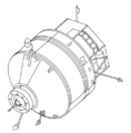


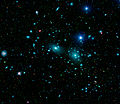


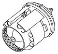


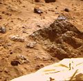
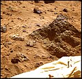

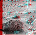
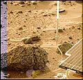

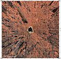

![Topographic map of the landing site, to a distance of 60 meters from the lander in the LSC coordinate system. The lander is shown schematically in the center; 2.5 meter radius circle (black) centered on the camera was not mapped. Gentle relief [root mean square (rms) elevation variation 0.5 m; rms a directional slope 4O] and organization of topography into northwest and northeast-trending ridges about 20 meters apart are apparent. Roughly 30% of the illustrated area is hidden from the camera behind these ridges. Contours (0.2 m interval) and color coding of elevations were generated from a digital terrain model, which was interpolated by kriging from approximately 700 measured points. Angular and parallax point coordinates were measured manually on a large (5 m length) anaglyphic uncontrolled mosaic and used to calculate Cartesian (LSC) coordinates. Errors in azimuth on the order of 10 are therefore likely; elevation errors were minimized by referencing elevations to the local horizon. The uncertainty in range measurements increases quadratically with range. Given a measurement error of 1/2 pixel, the expected precision in range is ~ 0.3 meter at 10 meter range, and ~ 10 meters at 60 meter range. Repeated measurements were made, compared, and edited for consistency to improve the range precision. Systematic errors undoubtedly remain and will be corrected in future maps compiled digitally from geometrically controlled images. Cartographic processing by U.S. Geological Survey. NOTE: original caption as published in Science Magazine Mars Pathfinder is the second in NASA's Discovery program of low-cost spacecraft with highly focused science goals. The Jet Propulsion Laboratory, Pasadena, CA, developed and manages the Mars Pathfinder mission for NASA's Office of Space Science, Washington, D.C. JPL is a division of the California Institute of Technology (Caltech).](https://upload.wikimedia.org/wikipedia/commons/thumb/3/37/PIA01152.jpg/106px-PIA01152.jpg)

